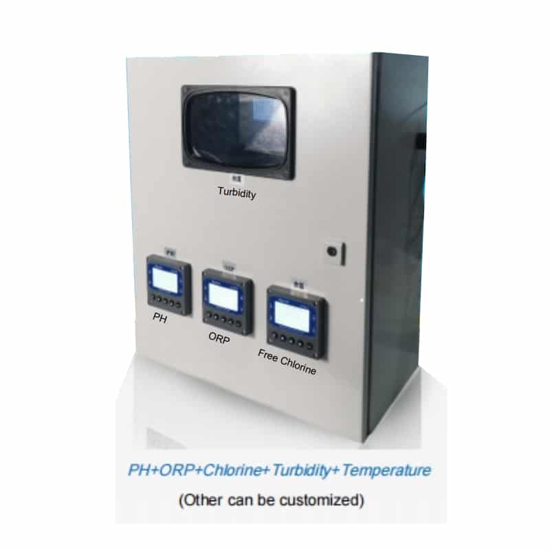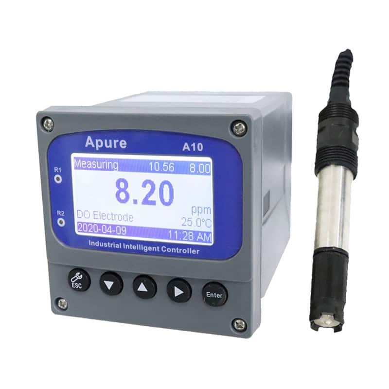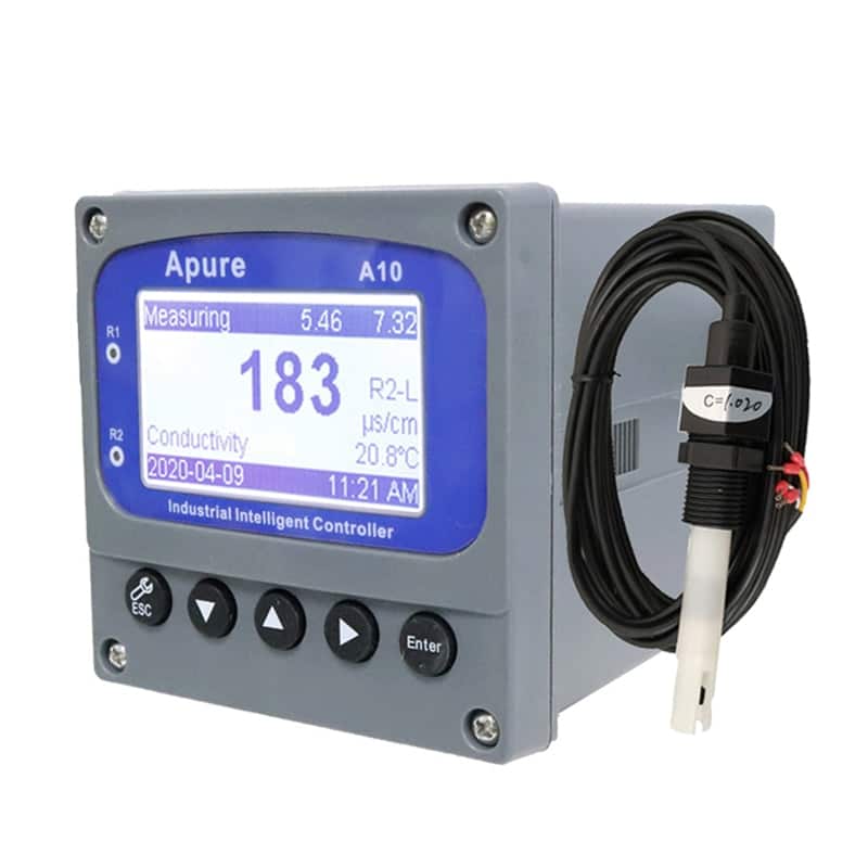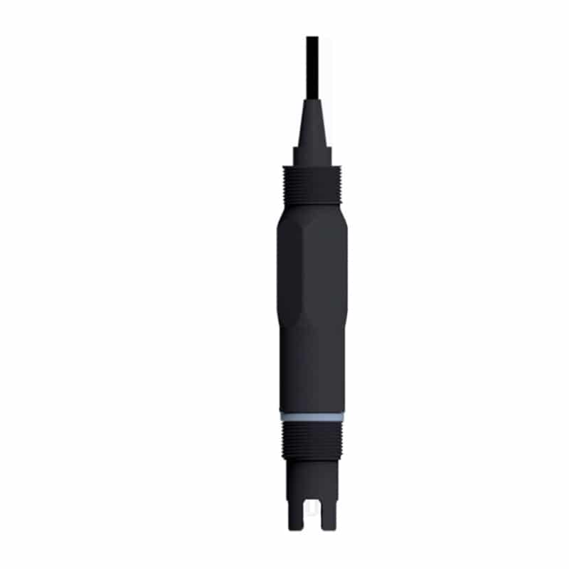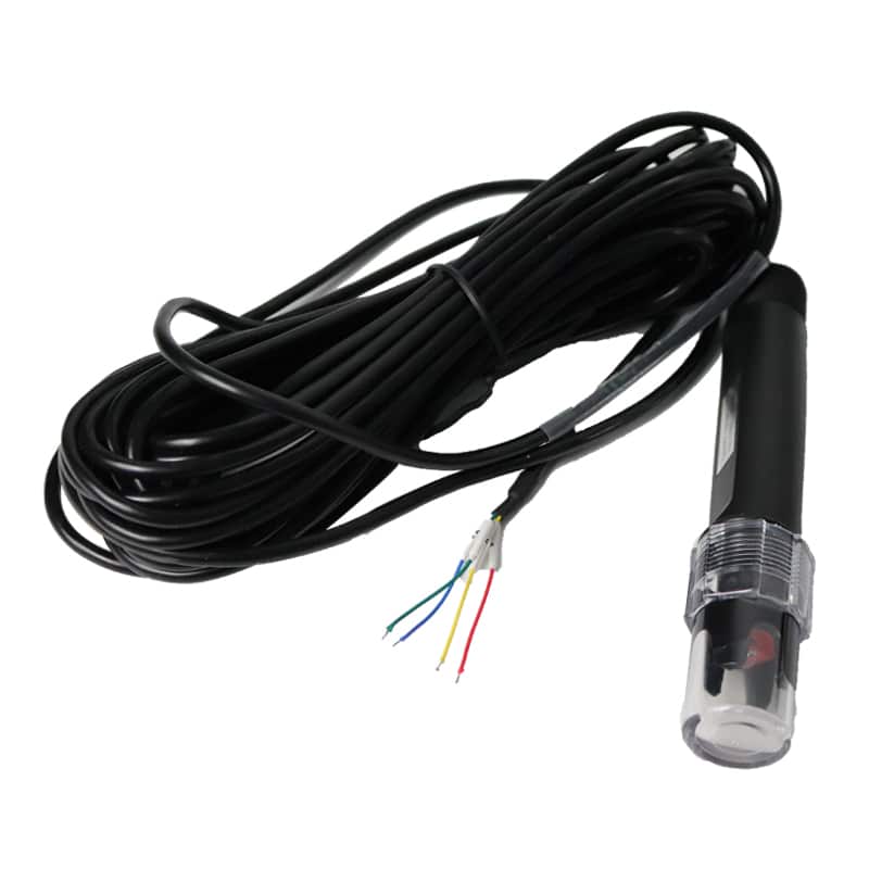
KS-02 Multiparameter Water Quality Monitoring Panel

The Apure KS-02 is a configurable water-quality monitoring panel. Specify the required sensor channels, sample-flow arrangement, controllers and any dosing equipment as a complete ordered assembly.
- Easy to operate
- Widely used
- Automation
The KS-02 panel is assembled for a selected monitoring task. Controllers, probes, flow cells, sampling components and any dosing equipment must be identified in the ordered bill of materials; their inclusion is configuration-dependent.
Specify the complete measurement system
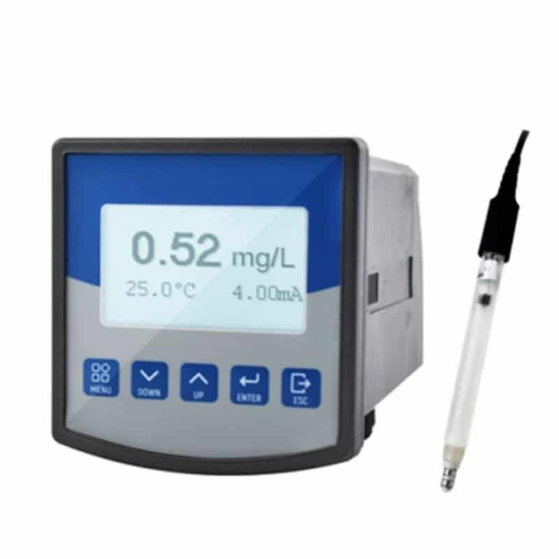
- List the required measurands and the actual sensor/controller combination for each. Confirm which channels are included, which are alternatives and which are optional additions.
- Specify sample inlet, flow, pressure, temperature, wetted materials, drainage and access for cleaning. The most restrictive component limit governs the approved installation; a controller temperature entry does not rate the complete wetted system.
- Identify the measurement method, range, unit and error basis separately for every channel. Check compensation settings before comparing readings, including EC/TDS conversion and DO pressure/salinity entries where applicable.
Listed measurement options
These entries summarize the existing options. They are not a statement that every channel is installed together, and they do not establish the final number of controller inputs.
| Listed option | Existing range reference | Selection requirement |
|---|---|---|
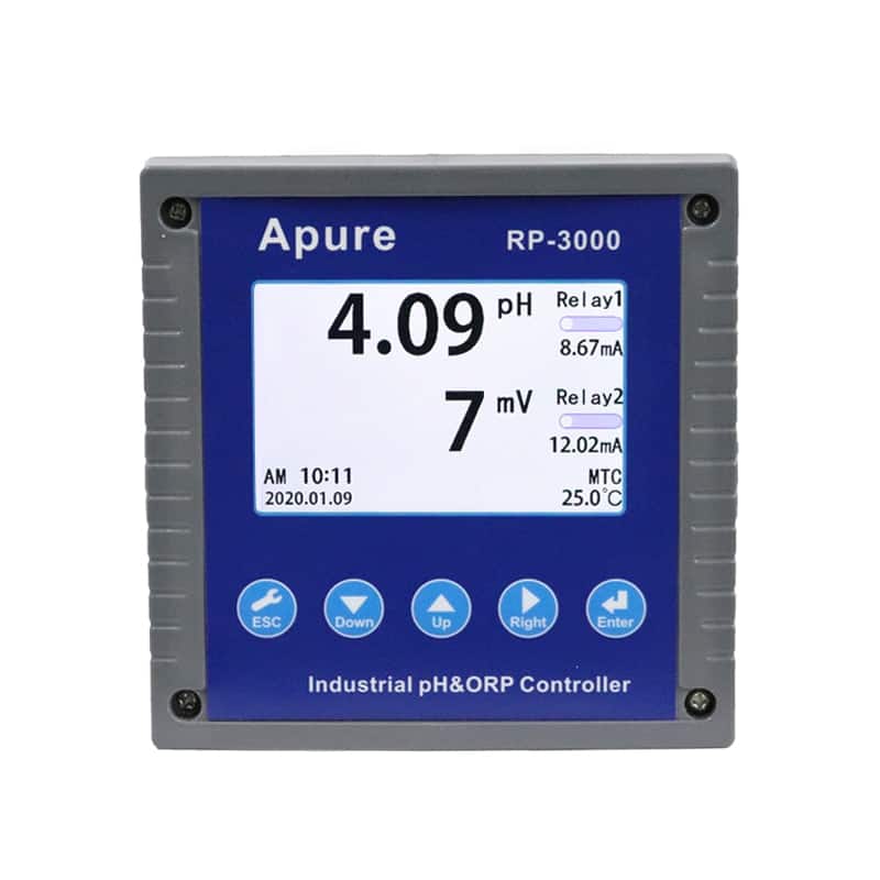
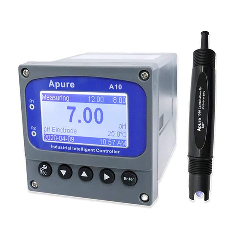
| pH / ORP | pH 0–14; ORP −1999 to 1999 mV | Select the actual paired probes, controller inputs and reference-electrode requirements. |
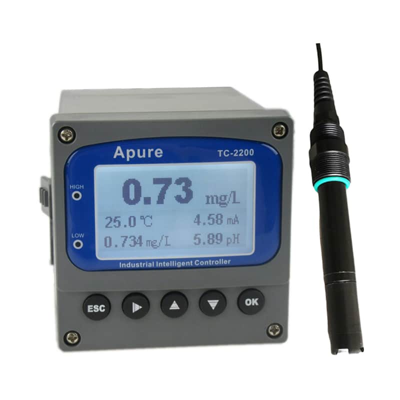
| Add free chlorine | Listed 0–20 ppm, amperometric probe | Confirm the chlorine species, flow cell, pH/temperature compensation and reference method. |
| Add turbidity | Listed 0–400 NTU, optical probe | Confirm the optical method, unit, selected range and calibration standards. |
| Add dissolved oxygen | Listed 0–20 ppm, membrane probe | The listed option refers to a membrane probe; use the procedure for the supplied technology and controller. |
| Add conductivity / TDS | Listed 0–200 mS/cm or 0–9999 ppm | EC and a derived TDS estimate use different units and settings; these two ranges are not a universal conversion. |
Panel installation
Confirm the panel’s actual footprint, mounting points, sample connections, instrument spacing and access for cleaning. Select the flow arrangement for the chosen sensors and keep the sample representative of the process.
Commissioning and handover
- Check each installed channel against its specified reference before enabling process control. Record the sensor and controller identities, standards, settings and independent verification results.
- For any dosing package, confirm the included pumps, controlled variable, control logic, permissives and loss-of-sample response in the supplied design. An output relay alone does not establish proportional-dosing capability.
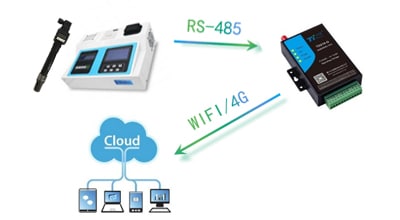
- Document the actual analog scaling and digital register map, units, timestamps and invalid-data handling. Set cleaning and calibration checks for the site and sensor type.
Listed electrical references
The existing main-board references list 100–240 VAC 50/60 Hz, a 230 VAC cable-box connection for an external dosing pump, and 250 V 10 A resistive-load relays. Confirm the supply and contact rating of each ordered component, the actual load and approved wiring. These references do not establish that a dosing pump is included or that every relay can supply every pump load.
The existing pH/ORP values, output entries and panel cut-out dimensions below are component-style references. Confirm their relationship to the ordered controller and complete assembly. They do not establish ranges for all optional sensors, the external panel/cabinet dimensions, or an approved sample temperature for the whole system.
| Brand | Apure |
|---|---|
| Model | KS-02 |
| pH/ORP reference range | PH: 0~14.00pH ORP: -1999 ~ 1999 mV |
| pH/ORP reference resolution | PH: 0.01PH ORP:1mV |
| pH/ORP reference accuracy | PH: 1%FS ORP:1%FS |
| Reference temperature entry | 0~135℃ |
| Controller output reference | Two 4-20mA outputs for pH and ORP |
| Controller relay reference | Two limited ON/OFF contact output(Relay) |
| Controller dimensions reference | 144×144×120mm |
| Controller cut-out reference | 138×138mm |