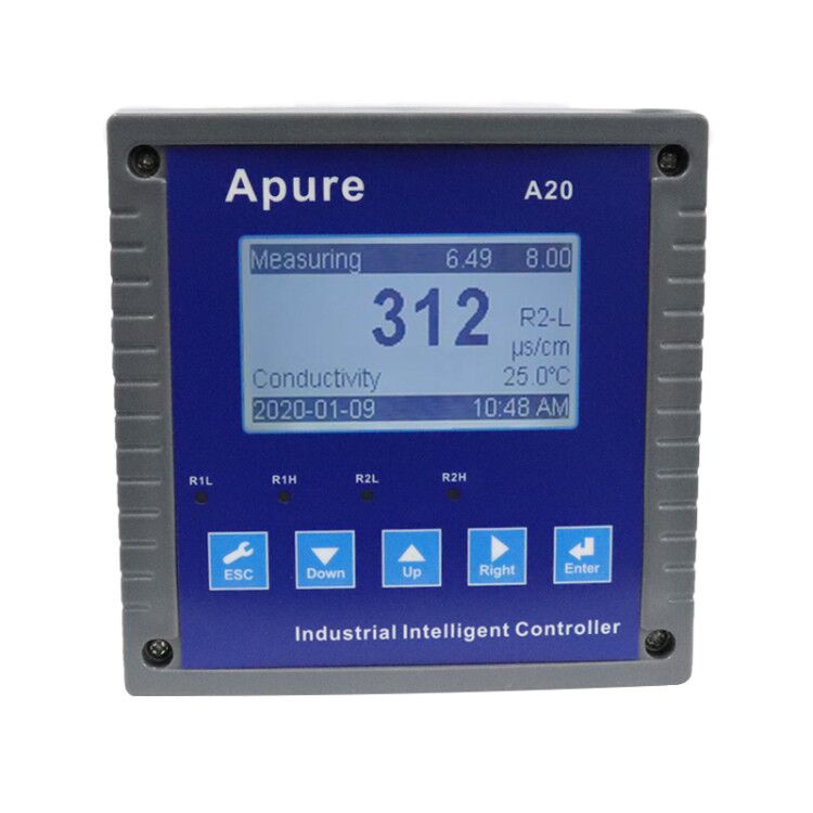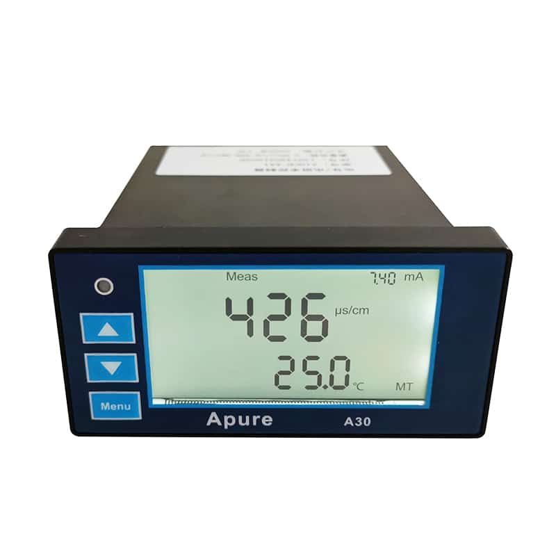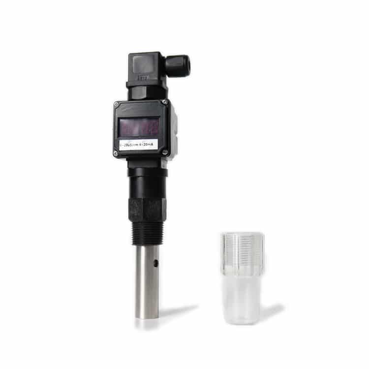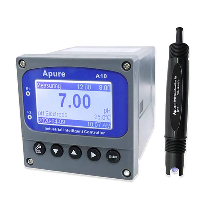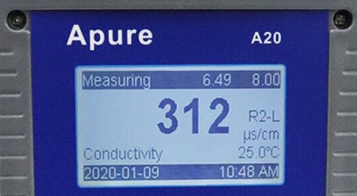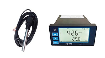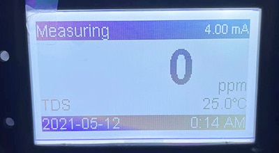
A10 EC Electrical Conductivity Meter


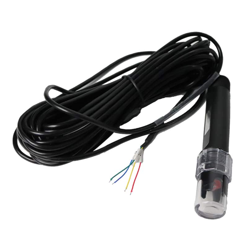
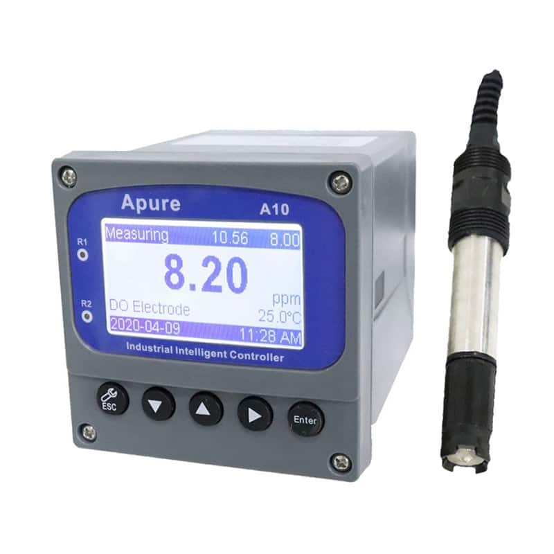
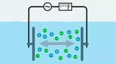
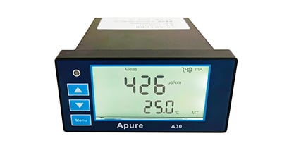
The Apure A10 EC Electrical Conductivity Meter monitors conductivity with a compatible probe. Estimated TDS depends on the selected conversion factor. Match the probe cell constant, temperature element and output configuration to the application.
- EC and estimated TDS
- Cell-constant selection
- Temperature and output configuration
A10 conductivity measurement
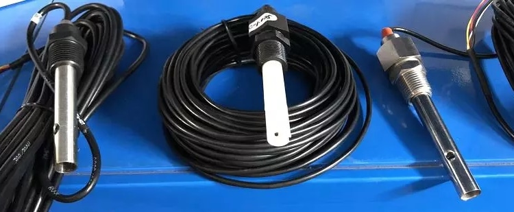
Use the probe option appropriate to the sample range. The ranges below are the listed probe/controller combinations; confirm the ordered configuration, low-end performance and temperature conditions in the supplied documentation. A range stated for one cell constant must not be applied to another probe.
| Listed nominal cell constant (cm⁻¹) | Listed conductivity range |
|---|---|
| 0.01 | 0.02–20.00 µS/cm |
| 0.1 | 0.2–200.0 µS/cm |
| 1.0 | 2–2000 µS/cm |
| 10.0 | 20–20000 µS/cm |
Characteristics
- Configure conductivity units and the temperature input for the actual probe.
- Set the reference temperature and compensation settings appropriate to the sample.
- If using TDS mode, select and document the factor validated for the water being measured.
- Confirm relay functions, output scaling and digital communication settings before connecting the control system.
Correspondence between TDS and conductivity
The following is an illustrative calculation at a selected TDS factor of 0.47, using conductivity referred to 25°C: estimated TDS (mg/L) = 0.47 × EC (µS/cm). This factor is not universal. For dilute water, a meter may label the estimate ppm; confirm its reporting convention. The examples do not establish the accuracy or resolution of a particular probe range.
| EC at 25°C (µS/cm) | Selected factor | Estimated TDS (mg/L) |
|---|---|---|
| 100 | 0.47 | 47 |
| 500 | 0.47 | 235 |
| 950 | 0.47 | 446.5 |
| 1000 | 0.47 | 470 |
| 1250 | 0.47 | 587.5 |
| 2000 | 0.47 | 940 |
For example, 1000 × 0.47 = 470 mg/L. A direct TDS reference test or a validated sample-specific factor is needed when the dissolved-solids result itself is critical. See EC versus TDS.

A10 EC listed configuration
The following controller information should be matched to the ordered version and compatible probe. Obtain the version-specific instructions before installation; a controller setting is not a probe pressure or temperature rating.
| Item | Listed information / confirmation |
|---|---|
| Brand / model | Apure / A10 EC |
| Probe ranges | See the cell-constant options in Overview; confirm the selected combination. |
| Accuracy | Listed as ±1% of full scale; confirm any additional digit term and operating conditions. |
| Temperature input | NTC10K / PT1000 are listed; confirm the fitted element and any other supported option. |
| Display | 2.4-inch LCD is listed. |
| Relays | Two relay outputs, listed at 250 VAC, 3 A; verify load type and wiring requirements. |
| Signal output | 4–20 mA and RS485; confirm the supplied Modbus RTU settings and register map. |
| Power supply | Listed 220 VAC ±10%, 50 Hz; confirm the nameplate before connection. |
| Dimensions and panel cutout | Confirm the approved outline, overall depth, rear clearance and cutout for the supplied version before fabrication. |