
Measuring liquid flow is essential in many industrial operations, where accuracy can determine profitability or prevent serious consequences. Most flow meters measure flow indirectly by assessing velocity, which depends on the pressure difference driving the liquid through a pipe. Given a constant cross-sectional area, flow rate is calculated as:
Q = V x A
Q = Flow rate of liquid through the pipe
V = Average flow rate
A = Cross-sectional area of the pipe
Liquid flow can be measured directly using positive displacement flow meters. These units divide the liquid into specific increments and continue to move. The total flow rate is the accumulation of the measured increments and can be counted mechanically or electronically.
Reynolds number
The performance of a flow meter is also influenced by the dimensionless unit called Reynolds number. It is defined as the ratio of the inertial force of a liquid to its resistance.
The formula is
R = 3160 x Q x Gt
D x ต
R = Reynolds number
Q = Flow rate of the liquid, gpm
Gt = Specific gravity of the liquid
D = Internal diameter of the pipe, in.
ต = Viscosity of the liquid, cp
Flow rate and specific gravity are the inertial forces, pipe diameter and viscosity are the resistance. For most liquid applications, the pipe diameter and specific gravity remain constant. At very low velocities or high viscosities, R is very low and the liquid flows in a smooth layer with the highest velocity at the center of the pipe, where viscous forces at the pipe wall limit it to very low velocities. This type of flow is called laminar flow. the R value is below about 2000. a characteristic of laminar flow is the parabolic shape of its velocity distribution.
However, most applications involve turbulent flow with R-values above 3000. turbulent flow occurs at high speeds or low viscosities. The flow breaks down into turbulent eddies that flow through the pipe with the same average velocity. The fluid velocity is less significant and the velocity distribution is more uniform in shape. A transition zone exists between turbulent and laminar flow. Depending on the pipe configuration and other installation conditions, the flow in this zone may be turbulent or laminar.
Types of liquid flow meters
Flow meters for closed pipe systems fall into four main types: differential pressure, positive displacement, velocity, and mass meters.
- Differential pressure meters (head gauges) include orifice plates, venturi tubes, flow nozzles, pitot tubes, and variable area meters.
- Positive displacement meters cover piston, elliptical-gear, disk, and rotary vane types.
- Velocity meters include turbine, vortex, electromagnetic, and acoustic designs.
- Mass meters consist of Coriolis and thermal types.
Differential Pressure flow meters
The use of differential pressure as an inferred measurement of the flow rate of a liquid is well known. By far, differential pressure flow meters are the most commonly used unit today. It is estimated that more than 50% of all liquid flow measurement applications use this type of unit.
The basic operating principle of differential pressure flow meters is based on the premise that the pressure drop across the meter is proportional to the square of the flow rate. The flow rate is obtained by measuring the differential pressure and extracting the square root.
Like most flow meters, differential pressure flow meters have a primary element and a secondary element. The primary element causes a change in kinetic energy, which creates a differential pressure in the pipe. The device must be properly matched to the pipe size, flow conditions and liquid characteristics. And, the accuracy of the element measurement must remain good within reasonable limits. The secondary element measures the differential pressure and provides a signal or reading that is converted to an actual flow value.
Orifice plate flow meters
Orifice plates are the most popular liquid flow meters in use today. An orifice is simply a flat piece of metal with a specific size hole drilled in it. Most orifices are concentric, but eccentric, conical (quadrant) and segmented designs are also available.
In practice, the orifice is installed in the pipe between two flanges. As the primary device, the orifice restricts the flow of fluid, thereby creating a differential pressure across the plate. Pressure measurement ports on both sides of the plate are used to detect the difference. The main advantages of orifice plates are that they have no moving parts and that their cost does not increase significantly with the size of the pipe.
Tapered and quadrant orifices are relatively new. These units were developed primarily for measuring liquids with low Reynolds numbers. An essentially constant flow coefficient can be maintained at an R-value below 5000. Tapered orifice plates have an upstream bevel, the depth and angle of which must be calculated and machined for each application.
The segment wedge is a variant of the segment orifice. It is a throttle orifice designed primarily to measure the flow of liquids containing solids. The device is capable of measuring flow at low Reynolds numbers and still maintaining the required square root relationship. Its design is simple and the wedge gap has only one critical dimension. The pressure drop through the device is only about half that of a conventional orifice plate.
The one-piece wedge assembly combines the wedge element and pressure measurement fitting into a one-piece pipe fitting bolted to a conventional pressure transmitter. No special piping or fittings are required to install the device in the pipeline.
The metering accuracy of all orifice flow meters depends on the installation conditions, the orifice plate area ratio, and the physical characteristics of the liquid being measured.
Venturi flow meters
The advantage of a venturi is its ability to handle large flows at low pressure drops. A venturi is essentially a section of pipe with a conical inlet and a straight throat. As the liquid passes through the throat, it increases in velocity, resulting in a pressure difference between the inlet and outlet regions.
Flow meters have no moving parts. They can be installed in large diameter pipes using flanged, welded or threaded end connections. The unit is usually fitted with four or more pressure measuring ports to average the measured pressure. Venturi tubes can be used for most liquids, including those with high solids content.
Flow tubes
Flow tubes are somewhat similar to venturi, except that they do not have an entrance cone. They have a tapered throat, but the outlet is elongated and smooth. The distance between the front and the tip is about one-half the diameter of the tube. The pressure measurement port is located about one-half the diameter of the tube downstream and one diameter upstream.
Flow nozzle
At high velocities, the flow nozzle can handle approximately 60% of the liquid flow compared to an orifice plate with the same pressure drop. Liquids containing suspended solids can also be metered. However, these devices are not recommended for high viscosity liquids or liquids containing large amounts of viscous solids.
Pitot tube flowmeter
The Pitot tube senses two types of pressure simultaneously, shock pressure and static pressure. The shock device consists of a tube with one end of the tube bent at right angles to the direction of flow. The end of the static tube is closed, but has a small slot in the side of the device. These tubes can be installed individually in the pipe or combined in a housing.
Pitot tubes are typically installed by welding a coupling to the pipe and inserting the probe through the coupling. The use of most Pitot tubes is limited to single point measurements. These devices are susceptible to clogging by foreign matter in the liquid. The advantages of Pitot tubes are low cost, no moving parts, easy installation and minimal pressure drop.
Elbow flowmeter
Elbow flow meters work on the principle that centrifugal forces are exerted along the outer edges as the liquid moves along a circular path. Thus, as the liquid flows through the pipe elbow, the force on the inner surface of the elbow is proportional to the density of the liquid multiplied by the square of its velocity. In addition, the force is inversely proportional to the radius of the elbow.
Arbitrary 90 degrees. Elbows can be used as liquid flow meters. All that is required are two small holes placed at the midpoint of the elbow (45 degree point) for the manometer tap. A pressure sensing line can be connected to the tap using any convenient method.
Target meter
The target meter senses and measures the force caused by the liquid striking the target or a drag disk suspended in the liquid stream. By measuring the force applied to the target the liquid flow rate can be directly indicated. In its simplest form, the meter consists only of an articulated oscillating plate that moves outward with the liquid flow. In this case, the device is used as a flow indicator.
More sophisticated versions use sophisticated low-level force sensor sensing elements. The target force caused by the liquid flow is sensed by a strain gauge. The output signal of the meter indicates the flow rate. The target meter can be used to measure the flow rate of dirty or corrosive liquids.
Variable area flow meter
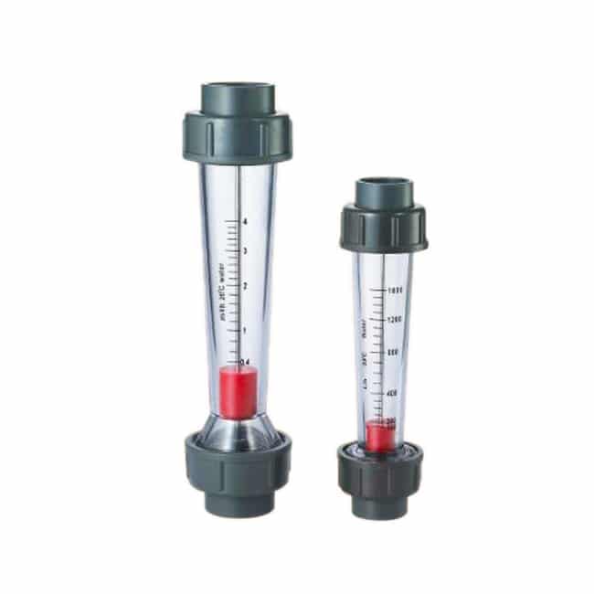
Variable area meters consist primarily of a conical tube and a float. Although classified as differential pressure devices, they are actually constant pressure devices. Flange end connections provide a simple way to install them in the pipe. Working principle of rotameter is when there is no liquid flow, the float is free to rest at the bottom of the pipe. When the liquid enters the bottom of the pipe, the float begins to rise. The position of the float varies directly with the flow rate. Its exact position is at the point where the pressure difference between the upper and lower surfaces balances the weight of the float.
Because the flow rate can be read directly on a scale mounted next to the tube, there is no need for an auxiliary flow reading device. However, if desired, an automatic sensing device can be used to sense the float level and transmit the flow signal. Variable area flow meter tubes are made of glass, metal or plastic. Tube diameters range from 1/4 to greater than 6 inches.
Positive displacement flow meter
The operation of these units consists of separating the liquid into precisely measured increments and continuing to move. Each segment is counted by a connection register. Because each increment represents a discrete volume, positive displacement units are popular in automatic dosing and accounting applications. Volumetric flow meters are ideal for measuring the flow of viscous liquids or where a simple mechanical flow meter system is required.
Reciprocating piston flowmeter
Reciprocating piston flow meters are available in single and multi-piston versions. The specific choice depends on the range of flow rates required in a particular application. Piston flow meters can be used to handle a wide range of liquids. The fluid never comes in contact with gears or other components that could clog or corrode.
Oval Gear Flow Meters
Oval gear flowmeters have two rotating oval gears with closely synchronized teeth. A fixed amount of fluid passes through the meter with each revolution. The shaft rotation can be monitored to obtain a specific flow rate.
Disc type meter
Chapter moving disc type meters have a movable disc mounted on a concentric sphere that is located in a spherical sidewall chamber. The pressure of the fluid passing through the measurement chamber causes the disc to oscillate in its circulation path without rotating about its own axis. It is the only moving part in the measurement chamber.
A pin extending vertically from the disk is connected to a mechanical counter, which monitors the oscillating motion of the disk. Each cycle is proportional to a specific flow rate. As with all positive displacement meters, changes in viscosity below a given threshold will affect the measurement accuracy. A wide range of sizes and capacities are available. These units can be made from a variety of construction materials.
Rotary vane gauges
Rotary vane meters are available in a variety of designs, but they all operate on the same principle. The basic unit consists of an equally divided rotating impeller (containing two or more compartments) mounted inside the instrument housing. The impeller is in constant contact with the housing. As the impeller rotates, a fixed volume of liquid is swept from each compartment to the outlet of the meter. The number of impeller revolutions is calculated and recorded in volume units.
Spiral flow meter
The helical flow meter consists of two radially inclined helical rotors that are gear driven together with minimal clearance between the rotors and the housing. The two rotors transfer the liquid from one end of the chamber to the other along the axial direction.
Velocity meters
These instruments operate linearly with respect to the volumetric flow rate. Because there is no square root relationship (as with differential pressure devices), they have a much larger range. Velocity meters are least sensitive to changes in viscosity when the Reynolds number exceeds 10,000. Most velocity meter housings are equipped with flanges or fittings to allow them to be connected directly into the piping.
Turbine flow meters
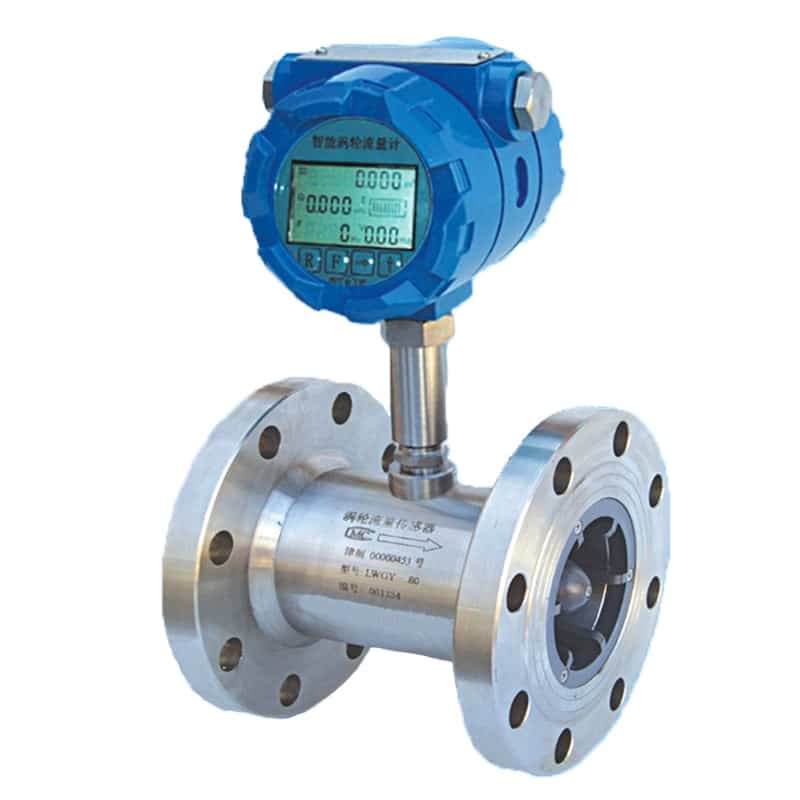
Turbine flow meters have been widely used for precise liquid measurement applications. The device consists of a multi-bladed rotor mounted in a pipe, perpendicular to the flow of the liquid. The rotor rotates as the liquid passes through the vanes. Rotational speed is a direct function of flow rate and can be sensed by magnetic sensors, photocells or gears. Electrical pulses can be counted and totalized.
The number of electrical pulses counted in a given time period is proportional to the flow rate. A tachometer can be added to measure the turbine speed and determine the liquid flow rate. A properly specified and installed turbine flow meter has good accuracy, especially for low viscosity liquids.
A major problem with turbine flowmeters is bearing wear. A “bearingless” design has been developed to avoid this problem. The liquid entering the flow meter passes through the spiral vanes of the stator, causing the liquid flow to rotate. The flow acts on the spheres, causing them to travel in the space between the first stator and the spiral-like second stator. The orbital motion of the sphere is detected electronically. The frequency of the generated pulse output is proportional to the flow rate.
Vortex flowmeters

Vortex flow meters take advantage of the natural phenomenon that occurs when a liquid flows through a blunt object. Vortex or vortex flow alternates downstream of the object. The frequency of the vortex shedding is proportional to the velocity of the liquid flowing through the flowmeter.
The three main components of the flow meter are the blunt object strut mounted on the meter bore, the sensor that detects the presence of vortices and generates an electrical pulse, and the signal amplification and conditioning transmitter whose output is proportional to the flow rate.
Electromagnetic flow meters
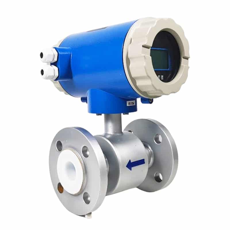
Magnetic flow meters can handle most liquids and slurries, provided that the material to be metered is electrically conductive. The main component is the flow tube (primary element), which is installed directly in the pipe. The pressure drop across the meter is the same as the pressure drop through the equivalent length of pipe, since there are no moving parts or flow obstructions. The voltmeter can be connected directly to the flow tube or remotely mounted and connected to the flow tube via a shielded cable.
Electromagnetic flow meters work according to Faraday’s law of electromagnetic induction, which states that a voltage is induced when a conductor passes through a magnetic field. The liquid acts as the conductor; the magnetic field is generated by an energized coil outside the flow tube. The amount of voltage generated is proportional to the flow rate. Two electrodes mounted on the wall of the tube detect the voltage measured by the secondary element.
Electromagnetic flowmeters offer major advantages: they can measure difficult and corrosive liquids and slurries; they can measure forward and reverse flow with equal accuracy. The disadvantages of early designs were high power consumption and the need to obtain a full tube with no flow to set the meter to zero initially. Recent improvements have eliminated these problems. The pulse-type excitation technique reduces power consumption because excitation occurs only half the time in the unit. A zero setting is no longer required.
Ultrasonic flow meters
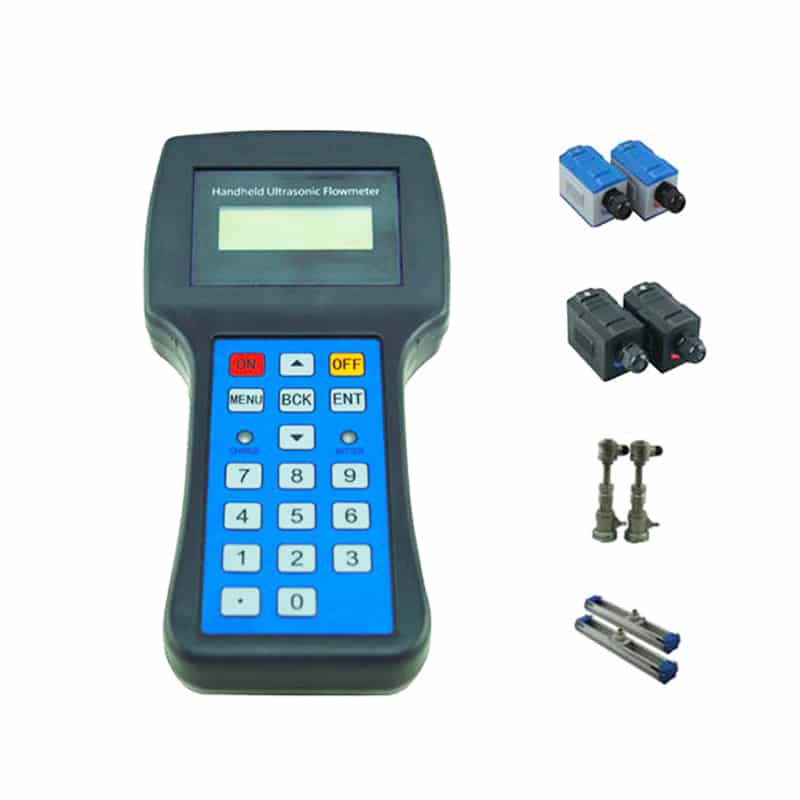
Ultrasonic flowmeters can be divided into doppler meters and travel time (or transverse) meters. Doppler meters measure the frequency shift caused by the flow of a liquid. Two sensors are mounted in a housing connected to one side of the pipe. A signal of known frequency is sent to the liquid to be measured. Solids, bubbles or any discontinuities in the liquid cause the pulse to be reflected to the receiver element. Since the liquid causing the reflection is moving, the frequency of the returned pulse is shifted. The frequency shift is proportional to the velocity of the liquid.
There is also a portable doppler meter that can be run on AC power or a rechargeable power pack. The instrument can be used by simply clamping the sensing head to the outside of the pipe. A set of 4 to 20 mA output terminals allows the unit to be connected to a strip chart recorder or other remote device.
The travel time meter’s sensors are mounted on each side of the pipe. The configuration allows the sound waves to travel between the devices at an angle of 45 degrees. angle to the direction of fluid flow. The speed of the signal propagating between the sensors increases or decreases with the direction of transmission and the speed of the liquid being measured. By transmitting the signal in both directions alternately, a time-differential relationship proportional to the flow rate can be obtained. A limitation of the travel time meter is that the liquid being measured must be relatively free of entrained gases or solids to minimize signal scattering and absorption.
Mass flow meter
Mass flowmeters the continued need for more accurate flow measurement in mass related processes (chemical reactions, heat transfer, etc.) has led to the development of mass flow meters. A variety of designs are available, but the most commonly used for liquid flow applications is the Coriolis meter. It operates on the basis of a natural phenomenon known as the Coriolis force, hence the name.
Coriolis flow meters
Coriolis meters are true mass meters that directly measure mass flow instead of volume flow. Since the mass is constant, the meter is linear and does not need to be adjusted for changes in liquid characteristics. It also eliminates the need to compensate for changing temperature and pressure conditions. The meter is particularly suitable for measuring liquids whose viscosity varies with velocity at a given temperature and pressure.
Coriolis meters are also available in a variety of designs. A popular unit consists of a U-shaped flow tube encapsulated in a sensor housing connected to an electronic unit. The sensing unit can be mounted directly into any process. The electronics unit can be located up to 500 feet away from the sensor.
Thermal mass flow meters
Thermal mass flowmeters are traditionally used for gas measurements, but are also available in designs for liquid flow measurements. These mass meters also operate independent of density, pressure and viscosity. Thermal mass meters use a heated sensing element that is isolated from the fluid flow path. The flowing stream conducts heat from the sensing element. The heat transferred is proportional to the mass flow rate. The sensor is never in direct contact with the fluid. The electronic assembly includes a flow analyzer, temperature compensator, and signal conditioner that provides a linear output proportional to the mass flow rate.
Open channel flow meter
An “open channel” is any pipe in which liquids flow on a free surface. This includes tunnels, unpressurized sewers, partially filled pipes, canals, streams and rivers. Of the many techniques that can be used to monitor flow in open channels, depth-related methods are the most common. These techniques assume that instantaneous flow can be determined from a measurement of water depth or head. Weirs and flumes are the oldest and most widely used primary devices used to measure flow in open channels.
Weirs work on the principle that an obstruction in a channel causes water to flow backwards, creating a high water level (head) behind the obstruction. The head is a function of the flow rate, and therefore the flow rate through the device. The weir consists of a vertical plate with a pointed top. The top of the plate can be straight or notched. Weirs are classified by the shape of the notch. The basic types are V-notched, rectangular and trapezoidal.
The discharge through the weir and flume is a function of the liquid level, so the device must use level measurement techniques to determine the flow rate. Staff gauges and floating operating units are the simplest devices to use for this purpose. Various electronic sensing, totalizing and recording systems are also available.
A recent development includes the use of ultrasonic pulses to measure liquid level. Measurements are made by sending an acoustic pulse from the sensor to the surface of the liquid and timing the return echo. Linearized circuitry converts the height of the liquid to a flow rate. A bar graph recorder records the flow rate and a digital totalizer records the total number of gallons. Another recently introduced microprocessor-based system uses ultrasonic or float sensors. A keypad with an interactive LCD display simplifies programming, control and calibration tasks.
Select a right liquid flow meter
Data shows that more than 75% of the flow meters installed in industry do not perform well. And poor selection accounts for 90 percent of these problems. Clearly, flowmeter selection is not a job for amateurs.
The most important requirement is to know exactly what the instrument should do. There are a number of issues to consider here. Will the measurement be used for process control (repeatability is the main concern) or for accounting or trade handover (high accuracy is important)? Is a local indication or a remote signal required? If a remote output is required, is it a proportional signal or a contact closure to start or stop another device? Is the fluid viscous, clean or slurry? Is it electrically conductive? What is its specific gravity or density? What flow rates are involved in the application? What is the operating temperature and pressure of the process? Accuracy (see glossary), range, linearity, repeatability, and piping requirements must also be considered.
It is equally important to understand what a flow meter cannot do as well as what it can do before making a final choice. Every instrument has strengths and weaknesses, and the degree of performance satisfaction is directly related to how well the instrument’s features and weaknesses match the application requirements. Often, the user’s expectations of flowmeter performance do not match those provided by the supplier. Most suppliers are eager to help customers select the right flowmeter for a particular job. Many provide questionnaires, checklists and specification sheets designed to obtain the critical information necessary to match the correct flowmeter to the job.
Technical improvements to the flowmeter must also be considered. For example, a common mistake is to select the design that was most popular for a given application several years ago and assume that it is still the best tool for the job. In recent years, many changes and innovations may have occurred in the development of flowmeters for specific applications, resulting in a wider range of choices.
Flow meters are available in a wide range of prices. Variable area flowmeters are usually the least expensive, with some smaller units costing less than $90. Mass flow meters are the most costly. They start at about $3000. However, the total system cost must always be considered when selecting a flowmeter. Installation, operation and maintenance costs are also important economic factors. For some of the more complex designs, maintenance costs can be high.
As with many other products, the plant engineer usually gets what he pays for when he buys a flow meter. But his satisfaction with the product will depend on the care he uses in selecting and installing the instrument. It comes back to understanding the process, the product and the flow metering requirements. It is not uncommon to “overbuy”. Plant engineers should not buy more powerful or complex flowmeters than they need.
Using flow meters
Although suppliers are always ready to provide flowmeter installation services, it is estimated that about 75% of users install their own equipment. But installation errors can occur. One of the most common situations is not allowing sufficient upstream and downstream straight pipe for the flowmeter.
Each design has some tolerance for erratic velocity conditions in the piping, but all installations require proper piping configurations to operate effectively. Proper piping provides the proper flow pattern for the device. Without it, accuracy and performance can be adversely affected. Flow meters are sometimes installed backwards (especially orifice plates). Pressure sensing lines can also be reversed.
For electrical components, intrinsic safety is an important consideration in hazardous areas. Most flowmeter suppliers offer intrinsically safe designs for this type of use.
Stray magnetic fields are present in most industrial plants. Power lines, relays, solenoids, transformers, motors and generators all contribute their share of interference. Users must ensure that the flowmeter they select is not subject to such disturbances. The problem occurs primarily with the electronics in the secondary components that must be protected. Strict adherence to the manufacturer’s recommended installation practices can often prevent such problems.
Calibration
All flow meters require an initial calibration. In most cases, the instrument is calibrated by the manufacturer for the specified conditions of use. However, if qualified personnel are available at the factory, the user can perform his own calibration.
The need for recalibration depends greatly on how well the meter is matched to the application. Certain fluids that pass through the meter tend to be abrasive, aggressive or corrosive. Over time, some parts of the device will degrade enough to affect performance. Some designs are more susceptible to damage than others. For example, wear on individual turbine blades can cause performance changes. If the application is critical, the accuracy of the flow meter should be checked frequently. In other cases, recalibration may not be required for many years because the application is not critical and would not otherwise change the meter’s performance. Some flowmeters require special equipment for calibration. Most manufacturers will provide such services at their plants or user facilities, and they will bring the equipment with them for on-site calibration.
Maintenance
Many factors can affect maintenance requirements and the expected life of a flow meter. The main factor, of course, is matching the correct instrument to the specific application. Poorly selected equipment will always cause problems early on. Flowmeters without moving parts usually require less attention than devices with moving parts. But all flowmeters will eventually require some kind of maintenance.
The primary element in a differential pressure flowmeter requires a lot of piping, valves and fittings when connected to the secondary element, so maintenance can be a recurring task in such installations. Pulse lines can become clogged or corroded and must be cleaned or replaced. And, improperly positioned secondary elements can lead to measurement errors. Repositioning elements can be expensive.
Flow meters with moving parts require periodic internal inspection, especially if the liquid being measured is dirty or viscous. Installing a filter before such devices will help reduce fouling and wear. Accessible instruments such as ultrasonic or electromagnetic meters may have problems with the electronics of their secondary components. Pressure transducers associated with secondary components should be removed and inspected periodically.
Applications where coatings may occur are also potential problems for accessible instruments such as magnetic or ultrasonic devices. If the coating is insulated, the operation of the magnetic flow meter can eventually be impaired if the electrodes are insulated from the liquid. This situation can be avoided by regular cleaning. With ultrasonic flow meters, the refraction angle may change and the acoustic energy absorbed by the coating can cause the flow meter to not work.
More articles on flow meters:
Relation between flow and pressure
Difference between flow meter and flow transmitter
Water level sensor types and works
Solution of water pollution