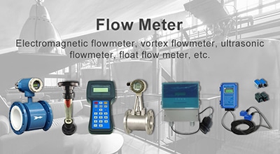
Flow Meter
Flow meters are used to measure the volumetric or mass flow rate of a liquid or gas. Apure’s range of flow meter instruments include magnetic, vortex, turbine, ultrasonic and rotameter.
The original flowmeter technologies were variable area, turbine, positive displacement and differential pressure. The newer technologies are less mechanized and more electronic, but all flowmeter technologies have been greatly improved by the addition of electronic enhancements, including protocols that support digital control. These flowmeters work in conjunction with other control elements (especially valves) to handle flow in manufacturing processes.
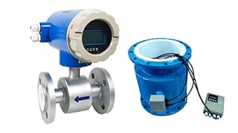
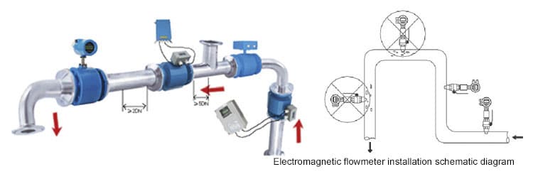
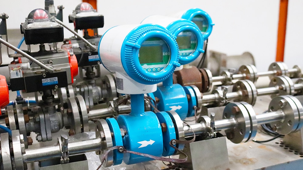
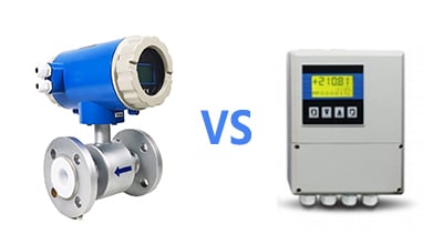
Magnetic flow meters, also known as mag meters, are widely used in a variety of industrial field applications due to their reliable flow rate measurements and features such as low-pressure loss and maintenance-free operation.
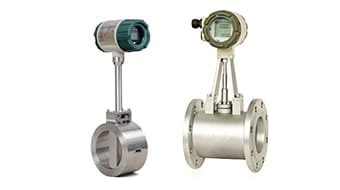
Vortex flow meters are long-lasting with field-proven sensor technology and high reliability, improving plant efficiency and reducing operating costs. It feature a unique sensor design that accurately identifies and eliminates noise.
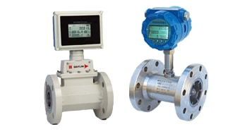
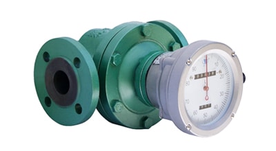
Turbine flowmeter is a precision flowmeter that, together with the corresponding meter, can measure the flow and total amount of liquid. And quantitative controller, high precision control into the fluid volume.
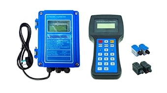
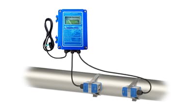
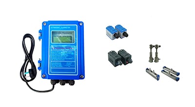
Apure ultrasonic flow meter uses the principle of low voltage, multi-pulse time difference, using high-precision and super-stable double balance signal detection transmission, differential reception digital detection technology.
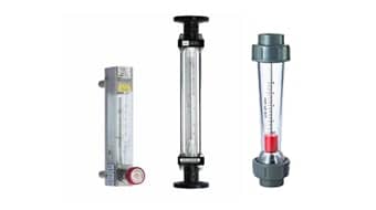
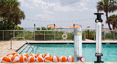
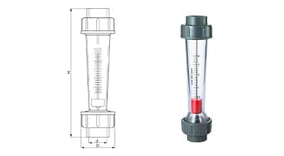
Variable area (VA) flow meters, or rotameters, are some of the oldest devices used for flow measurement, known for their flexibility across various applications and high reliability. Simple installation and trouble-free operation.
What is a flow meter?
Flow meter (or flow transmitter, flow sensor, flow indicator) is an instrument used to measure the linear, nonlinear, mass or volumetric flow of a liquid or gas. When selecting a flow meter, intangible factors such as the familiarity of plant personnel at a particular plant site, their calibration and maintenance experience, spare parts availability, and the average time between failures history should be considered. It is also recommended that installation costs be calculated only after these steps have been taken.
Applications
Industrial production process
As a process automation control system detection instrument:
- Used to measure the flow of various fluid media in the production process, such as raw materials, fuels, intermediate products and finished products, etc., to provide the necessary parameters for the control of the production process.
- Used to monitor abnormal conditions in the production process, such as leakage, blockage, etc., and take timely measures to prevent accidents.
Total meter for measuring the quantity of materials:
- Used to measure the consumption of raw materials, fuels, intermediate products and finished products in the production process, providing the basis for costing and production management.
- Used to measure the sales volume of products, providing the basis for enterprise accounting profit.
Energy measurement
- Water metering: measuring water flow in the fields of tap water supply, agricultural irrigation, industrial water and sewage treatment.
- Gas metering: measuring the flow of artificial gas, natural gas and other combustible gases, to provide a basis for gas production, transportation and sales.
- Steam metering: measuring the flow of steam used in power plants, chemical plants and other industrial enterprises, providing the basis for boiler combustion and production process control.
- Oil metering: Measure the flow of crude oil, refined oil and other petroleum products to provide a basis for oil production, transportation and sales.
Environmental protection engineering
- Air pollutant emission monitoring: Measurement of flue gas flow rate, to provide a basis for flue gas desulfurization and denitrification and other pollutant management facilities operation and control.
- Sewage discharge monitoring: measuring sewage flow, providing basis for the operation and control of sewage treatment plant.
- Solid Waste Treatment: Measurement of solid waste transportation, to provide a basis for the operation and control of solid waste treatment facilities.
Other applications
- Transportation: measuring the flow of media transported by pipelines, such as oil, natural gas, water, etc.
- Construction engineering: measuring the flow of construction materials such as concrete, mortar, etc.
- Medical and health care: to measure the flow of medical liquids such as blood, medicines, etc.
- Scientific research: measuring the flow characteristics of fluids, such as flow rate, flow rate, etc.
Types of flow meters
There are many types of flow meters, but they can be divided into the following categories based on their operating principle:
- Velocity type flowmeter: calculates the flow rate by measuring the flow velocity of the fluid. Common velocity type flowmeters include Pitot tube, Venturi flowmeter and impeller flowmeter.
- Mass flowmeter: by measuring the mass of the fluid to calculate the flow rate. Common mass flowmeter including turbine flowmeter, vortex flowmeter and Coriolis flowmeter.
- Volumetric flowmeter: by measuring the volume of the fluid to calculate the flow rate. Common volumetric flowmeter including oval gear flowmeter and Roots flowmeter.
Here are some other types of flow meters:
- Electromagnetic flowmeter: the use of Faraday’s law of electromagnetic induction to measure the flow of conductive fluids.
- Ultrasonic flowmeter: Measures the flow rate by utilizing the propagation velocity of ultrasonic waves in a fluid.
- Differential Pressure Flow Meter: Measure the flow rate by utilizing the differential pressure generated when the fluid flows through the throttling device.
- Thermal flowmeter: Using the cooling effect of the fluid on the thermal element to measure the flow rate.
How to choose a flowmeter?
Before choosing a flow sensor, there are 9 questions that need to be answered.
- What is the fluid being measured?
- Do you need rate measurement and/or totalization?
- If the fluid is not water, what is the viscosity of the fluid?
- Do you need a local display on the flow meter or do you need an electronic signal output?
- What are the minimum and maximum flow rates?
- What are the minimum and maximum process pressures?
- What are the minimum and maximum process temperatures?
- Is the fluid chemically compatible with the flowmeter’s wetted parts?
- If this is a process application, what is the pipe size?
The first step in selecting the right flow meter
First step in selecting a flow sensor is to determine whether the flow information should be continuous or cumulative, and whether the information is required locally or remotely. If remote, should the transmission be analog, digital, or shared? And, if shared, what is the required (minimum) data update frequency? Once these questions have been answered, the properties and flow characteristics of the process fluid as well as of the pipeline housing the flow meter should be evaluated.
Fluid and flow characteristics
Lists the fluid and its given pressure, temperature, allowable pressure drop, density (or specific gravity), conductivity, viscosity (is it in Newtons?) and vapor pressure at the maximum operating temperature, and how these properties may indicate changes or interactions. In addition, all safety or toxicity information should be provided, as well as detailed data on fluid composition, presence of air bubbles, solids (abrasive or soft, particle size, fibers), coating tendencies and translucent quality (opaque, translucent) or transparent?) .
Pressure and temperature range
When selecting a flow meter, the expected minimum and maximum pressure and temperature values should be given in addition to the normal operating values. The fact whether the flow will be reversed, whether it does not always fill the pipe, whether agglomerated flows (air-solid-liquid) will form, whether inflation or pulsation is possible, whether sudden changes in temperature will occur or whether special precautions are required for maintenance during cleaning and purging should also be stated.
Piping and installation area
With respect to the area in which the piping and flow meter are located, consider: For piping, its orientation (to avoid downward flow in liquid applications), size, material, schedule, flange pressure rating, accessibility, upward or downward turns, valves, regulators, and length of available straight pipe section. The specifying engineer must know if vibration or magnetic fields are present or likely to be present in the area, if electrical or pneumatic power is present, if the area is classified as an explosion hazard, or if there are other special requirements, such as compliance with sanitation or cleanliness requirements.
Flow rate and accuracy
The next step is to determine the required meter range by determining the minimum and maximum flow rate (mass or volume) that will be measured. After that, the required accuracy of the flow measurement is determined. Typically, accuracy is specified as a percentage of actual reading (AR), a percentage of calibration range (CS), or a percentage of full scale (FS) units. Accuracy requirements should be stated separately at minimum, normal, and maximum flow rates. Unless you understand these requirements, the performance of your meter may not be acceptable over its entire range.
In applications where products are sold or purchased based on meter readings, absolute accuracy is critical. In other applications, repeatability may be more important than absolute accuracy. Therefore, it is recommended that the accuracy and repeatability requirements for each application be determined separately and that both be stated in the specification.
When the accuracy of a flow meter is expressed in % CS or % FS units, the absolute error will rise as the measured flow rate decreases. If the meter error is expressed in % AR, the absolute error remains constant at high or low flow rates. Because the full scale range (FS) is always larger than the calibration range (CS), a sensor with % FS performance will always have a larger error than a sensor with the same % CS specification. Therefore, to fairly compare all bids, it is recommended that all quoted misstatements be converted to the same % AR units.
In carefully prepared flow meter specifications, all accuracy statements are converted to uniform % AR units, and these % AR requirements are specified for minimum, normal, and maximum flow rates, respectively. All flowmeter specifications and bids should clearly state the accuracy and repeatability of the flowmeter at minimum, normal, and maximum flow rates.
Accuracy and repeatability
If acceptable metrology performance can be obtained from two different meter classes and one has no moving parts, choose the one with no moving parts. Moving parts are a potential source of problems, not only for the obvious reasons of wear, lubrication and sensitivity to coatings, but also because moving parts require clearance space, which can sometimes introduce “slop” in the measured flow. Even with well-maintained and well-calibrated instruments, this unmeasured flow can vary with fluid viscosity and temperature. Temperature changes can also alter the internal dimensions of the meter and require compensation.
In addition, if the same performance can be obtained from a full flow meter and a point sensor, a flow meter is usually recommended. Because point sensors do not view the full flow rate, they can only be read accurately if they are inserted to a depth where the flow rate is the average of the flow rate distribution in the pipe. Even if this is carefully determined during calibration, it is unlikely to remain constant because the velocity profile will vary with flow rate, viscosity, temperature and other factors.
Mass or volume units
Before specifying a flow meter, it is also recommended to determine if flow information expressed in mass or volume units is more useful. Volumetric flow is not very meaningful when measuring the flow of compressible materials, unless the density (and sometimes viscosity) is constant. When measuring the velocity (volumetric flow) of incompressible liquids, the presence of suspended air bubbles can cause errors; therefore, air and gas must be removed before the fluid reaches the meter. In other velocity sensors, pipe lining may cause problems (ultrasonic) or the meter may stop working if the Reynolds number is too low (in vortex flowmeters, RD > 20,000 is required).
Given these considerations, mass flow meters are insensitive to changes in density, pressure and viscosity and are unaffected by changes in Reynolds number and should be kept in mind. Also underutilized in the chemical industry are various flumes that measure the flow of partially full tubes and can pass large floating or settleable solids.
Mass flow or volume flow?
So you want to measure the flow rate? The answer seems to be to buy a flow meter. Defining fluid flow as the amount of fluid flowing through a given location seems simple enough – any flow meter will suffice. However, consider the following equation describing the flow of fluid in a pipe.
Q = A xv
Q is the flow rate, A is the cross-sectional area of the pipe, and v is the average fluid velocity in the pipe. Putting this equation into practice, the flow rate of fluid through a pipe with a cross-sectional area of 1 square meter at an average velocity of 1 meter per second is 1 cubic meter per second. Note that Q is the volume per unit of time, so Q is usually expressed as a “volumetric” flow rate. Now consider the following equation.
W = rho x Q
where W is the flow rate (read again) and rho is the fluid density. Putting this equation into action, when a fluid with a density of 1 kg/m3 is flowing at 1 cubic meter per second, the flow rate will be 1 kg/sec. (You can do the same for the commonly used “pounds”. No need to elaborate – assume pounds is the unit of mass.) Note that W is the mass per unit of time, so W is usually expressed as “mass” “flow rate. Now – which flow rate do you want to measure? Not sure? In some applications, the volumetric flow rate needs to be measured.
Consider filling the tank. Volumetric flow may make sense to avoid overflowing a tank that can be added with different density liquids. (Again, level transmitters and high level switches/shutoffs may not be required for flow meters.) Consider controlling the flow of fluid into a process that can only accept a limited volume per unit of time. Volumetric flow measurement seems to apply.
In other processes, mass flow is important. Consider a chemical reaction that requires the reaction of substances A, B and C. What is of interest is the number of molecules present (their mass), not their volume. Similarly, when buying and selling products (regulatory transfers), mass is important, not quantity.
How much maintenance does a flow meter require?
Many factors can affect maintenance requirements and the expected life of a flow meter. The main factor, of course, is matching the correct instrument to the specific application. Poorly selected devices will always cause problems early on. Flowmeters without moving parts usually require less attention than devices with moving parts. But all flowmeters will eventually require some kind of maintenance.
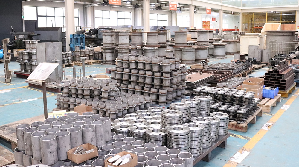
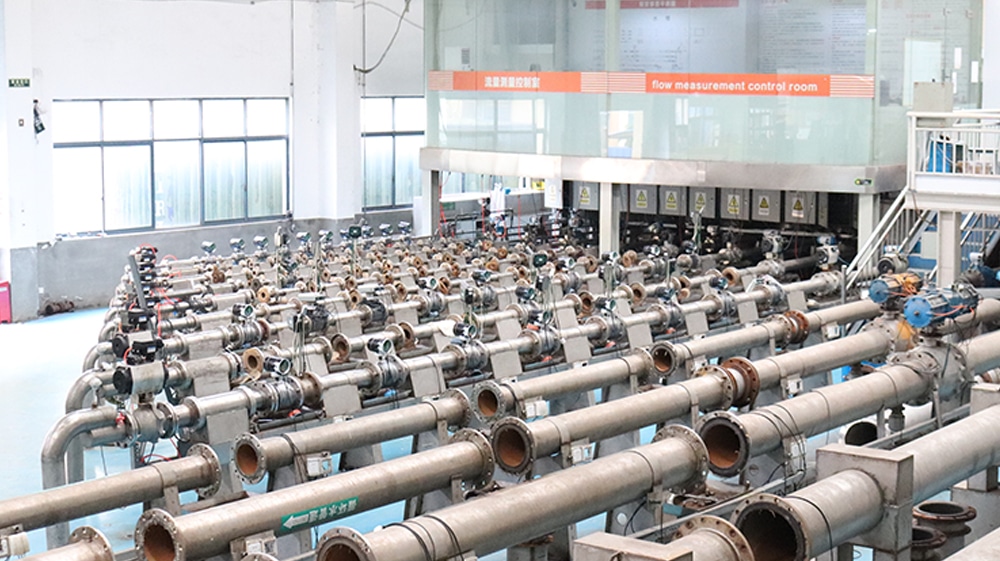
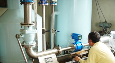
Flowmeter factory
Videos
FAQ
Popular articles
Flow meter calibration
What is doppler flow meter?
Liquid Flow Meter
Select the right water flow meter for you
Sewage flowmeter
Working principle of rotameter
Hot water flow meter
Chilled water flow meter
Types of IoT sensors
Difference between flow meter and flow transmitter

Select right irrigation flow meter
How does an open channel flow meter work?
What is positive displacement flow meter?
Useful information about flow units
What is a flow sensor?