
A level transmitter measures a liquid or bulk-solid level continuously and sends the result to a controller, display or monitoring system. Common technologies include float, displacer, hydrostatic pressure, differential pressure, radar, guided wave radar, ultrasonic and capacitance. The best choice depends on the medium and vessel conditions, not simply the measuring range.
Continuous level transmitter or point level switch?
A continuous transmitter reports level across a range, for example as 4–20 mA or a digital value. A point level switch indicates whether material has reached a selected height. A float can form part of either design, and a magnetic level gauge may provide local indication with an optional transmitter or switch. Check the actual output and function before comparing products.
Compare the main level transmitter types
On a phone, swipe comparison tables sideways to see every column.
| Technology | How it measures | Contact with medium | Main selection limits |
|---|---|---|---|
| Float / magnetic float | A float follows the surface; its position is detected or transmitted. | Yes | Buoyancy depends on liquid density; moving parts and chambers may be affected by coating or solids. |
| Displacer (buoyancy) | Changing immersion changes buoyant force on a suspended element. | Yes | Density changes affect the result; distinguish a displacer from a float that moves with the surface. |
| Hydrostatic pressure | Bottom pressure is converted to liquid height using density. | Usually yes | Changing density, vent condition, deposits and tank pressure need consideration. |
| Differential pressure (DP) | Pressure difference between process connections is used to infer liquid head. | Usually yes, directly or through seals | Closed-tank reference arrangement, wet legs, seals and density affect the calculation. |
| Free-space radar | Microwave signals travel to the surface and return; distance is converted to level. | No probe in liquid for typical top-mounted designs | Dielectric properties, foam, nozzle geometry, obstructions and echoes still need assessment. |
| Guided wave radar | Microwave signals travel along a rod or cable probe and reflect at a material boundary. | Yes | Probe coating, bridging, mechanical loads and installation clearances matter. |
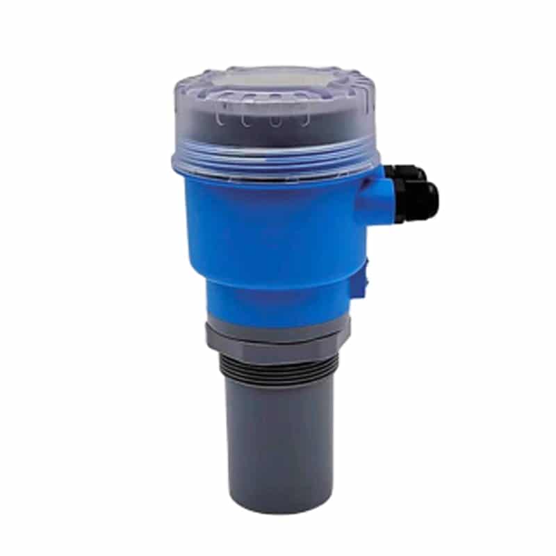
| Ultrasonic | Sound pulses reflect from the surface; travel time gives distance. | Usually noncontact | Foam, vapor, temperature gradients, turbulence and the near-sensor dead zone can affect echoes. |
| Capacitance | Changing material coverage changes capacitance around an electrode. | Usually yes | Dielectric changes, conductive media, insulation and buildup must match the probe design. |
Choose by the actual tank conditions
| Application condition | Technologies to assess | What must be resolved |
|---|---|---|
| Open tank with clean water | Ultrasonic, radar or hydrostatic | Mounting height, dead zone, turbulence, immersion and required resolution. |
| Foam, steam or heavy vapor | Radar, guided wave radar or pressure-based measurement | Foam can attenuate or create echoes; pressure methods avoid surface echoes but require reliable density and pressure references. Validate the specific model. |
| Pressurized closed tank | DP with an appropriate reference arrangement, or a pressure-rated radar design | A simple vented open-tank calculation cannot separate gas pressure from liquid head. Check seals, reference legs and pressure rating. |
| Liquid with changing density | Radar or ultrasonic where surface conditions permit | Hydrostatic and buoyancy methods need density correction or a justified density assumption. |
| Sticky, coating or solids-bearing liquid | Noncontact radar where suitable; maintainable contact designs where needed | Check antenna buildup, probe coating, bridging and access for cleaning. |
| Narrow vessel, internal pipes or agitator | A suitable radar beam, guided probe or pressure installation | Map obstructions, nozzle position, probe clearance and false echoes. |
| Corrosive liquid or no-contact requirement | A suitable noncontact design or compatible wetted materials | An external-looking installation may still have process-exposed seals or antennas. Verify every exposed component. |
| Bulk solids | Radar, ultrasonic or a guided probe specifically rated for solids | Consider dust, fill streams, sloped surfaces and probe tensile loads; do not assume a liquid model is suitable. |
These are shortlists, not universal recommendations. Temperature, pressure, chemical compatibility, hazardous-area certification and the complete mounting assembly must be checked against the selected model. There is no single technology that is immune to every type of foam, buildup or installation error.
How the working principles differ
Float and displacer transmitters
A float must remain buoyant and move freely. A displacer generally remains suspended while the force on it changes with immersion. Both use buoyancy, but they do not measure in the same mechanical way. Coating, density and mechanical obstruction can affect their performance.


Radar and guided wave radar
Radar uses electromagnetic signals. Free-space radar measures from an antenna toward the surface; guided wave radar directs the signal along a probe. Neither needs the speed of sound to determine distance. However, dielectric contrast and the installation still determine whether a usable reflection can be detected.

Ultrasonic level transmitters
An ultrasonic sensor measures the return time of a sound pulse. Temperature compensation helps account for sound-speed changes, but strong thermal gradients, vapor composition or foam may still make the echo unreliable. Leave the model’s specified blanking distance above the highest expected level and keep the sound path clear.

Hydrostatic and differential pressure transmitters
For an open tank with an appropriate atmospheric reference, liquid head follows P = ρgh, so h = P/(ρg). Here P is the pressure due to the liquid column, ρ is liquid density and g is gravitational acceleration. For a closed tank, gas-space pressure must be accounted for, often by a properly arranged DP measurement. Wet legs, remote seals and installation elevations can introduce additional offsets.
Illustrative calculation: if a water-like liquid has an assumed density of 1,000 kg/m³, a 2.00 m head produces approximately 19.6 kPa using g = 9.81 m/s². If the real density changes, the height inferred using that fixed assumption changes. This is a physics example, not a model accuracy specification.
Capacitance level transmitters
The sensor responds to capacitance changes as material covers more of the probe. The selected electrode, insulation and calibration must match the medium. A change in composition or dielectric properties can look like a level change, while deposits can create a persistent offset. Some designs are point switches rather than continuous transmitters.
Installation and commissioning checklist
- Define minimum and maximum operating levels, vessel dimensions, pressure, temperature, density variation, foam, solids and cleaning conditions.
- Choose a measurement reference. For top-mounted distance measurement, level often equals reference height minus distance, with installation offsets included.
- Confirm access, mounting orientation, dead zone, beam or probe clearance, cable protection and process compatibility. Keep away from fill streams or agitators where the model requires it.
- Configure the measurement range, units and output scaling. A linear 4–20 mA output normally maps 4 mA to the configured lower value and 20 mA to the upper value; it is not automatically a volume signal.
- Verify at known levels or against a suitable reference across the operating interval. Record empty/full references, offsets, density assumptions and output checks.
- Document maintenance and fault handling. Check for lost echo, blocked vents, probe buildup, chamber blockage or wiring faults before changing calibration.
For a theoretical 0–4 m linear level output, 12 mA represents 2 m. An irregular tank requires a separate level-to-volume relationship, so 50% level does not necessarily mean 50% volume. For signal calculations and pressure references, see pressure transmitter principles and 4–20 mA scaling.
For a method-specific commissioning plan, use the level transmitter calibration guide; for echo-based distance and empty/full setup, see ultrasonic level transmitter calibration. Confirm the model’s reference point, dead zone and procedure before adjusting any setting. Checking the sensor, scaling the output and converting level to tank volume are separate tasks.
Apure level measurement options
Compare ultrasonic level sensors, hydrostatic level sensors and magnetic level gauges within the Apure level measurement range. The product names identify options to investigate; the current datasheet and process details determine suitability.




Frequently asked questions
Is radar always better than ultrasonic?
No. Radar can be preferable when sound propagation is unreliable, but measurement performance and cost depend on the surface, vessel and required range. Compare the application limits and installation requirements of actual models.
Can one transmitter measure both interface and total level?
Only if its sensing principle, probe, configuration and material properties support that measurement. An interface application needs a separate assessment; a standard continuous level output does not imply interface capability.