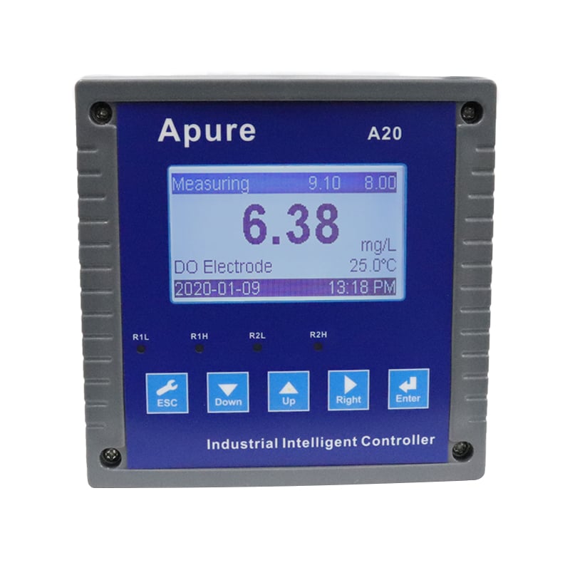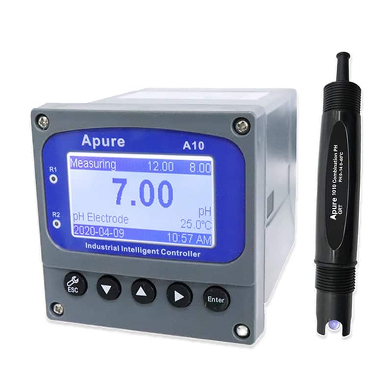
A10 Optical Dissolved Oxygen Meter


Specify the Apure A10 dissolved-oxygen controller together with its compatible probe. For an optical DO system, confirm the optical probe model, signal input and calibration procedure as one matched configuration. The probe technology determines maintenance and compensation requirements.
- Matched controller and probe
- DO and temperature monitoring
- Configuration-specific calibration
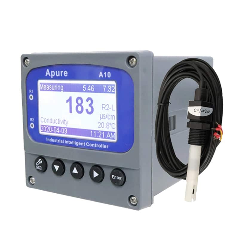
A10 dissolved-oxygen system
Request the optical DO configuration and its supported probe when obtaining a quotation. Optical probes determine oxygen through luminescence quenching; polarographic probes use an electrochemical system. Do not infer compatibility or copy a polarization, membrane or electrolyte procedure from one technology to the other.
Characteristics
- Confirm DO concentration units, temperature input and the selected probe’s operating range.
- Check which alarm, analog-output and digital-communication options are fitted.
- Set output scaling and alarms for the application after verifying the measurement.
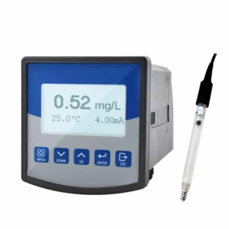
- Use the calibration and maintenance instructions for the connected probe, not a generic controller illustration.
Temperature, pressure and salinity compensation
Air-saturated water does not have one universal DO concentration. The expected mg/L value changes with temperature, barometric pressure and salinity. Use the approved meter algorithm or an authoritative calculation with those conditions specified; an unqualified temperature table is not a calibration standard.
| Factor | What to verify |
|---|---|
| Temperature | A stable, correctly measured sample temperature and compatible temperature element. |
| Pressure | The required local barometric-pressure input or compensation method; do not substitute a sea-level weather correction without checking the manual. |
| Salinity | Whether a salinity value must be entered or is measured by the system, and the scale used. |
| Calibration | The optical probe’s specified air/saturation or other reference procedure, acceptance criteria and cap-data requirements. |
For an optical probe, inspect and clean the sensing cap as instructed. Do not automatically apply electrolyte replacement or polarographic warm-up steps. Keep the sensor and sample at stable conditions and allow the reading to stabilize. Compare DO technologies and calibration workflows.

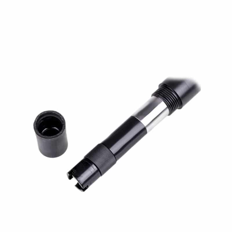
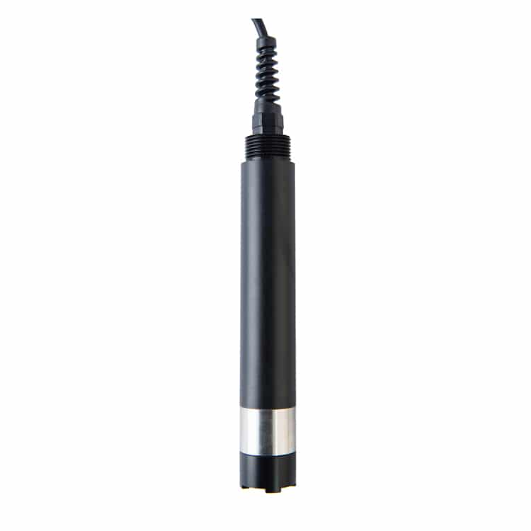
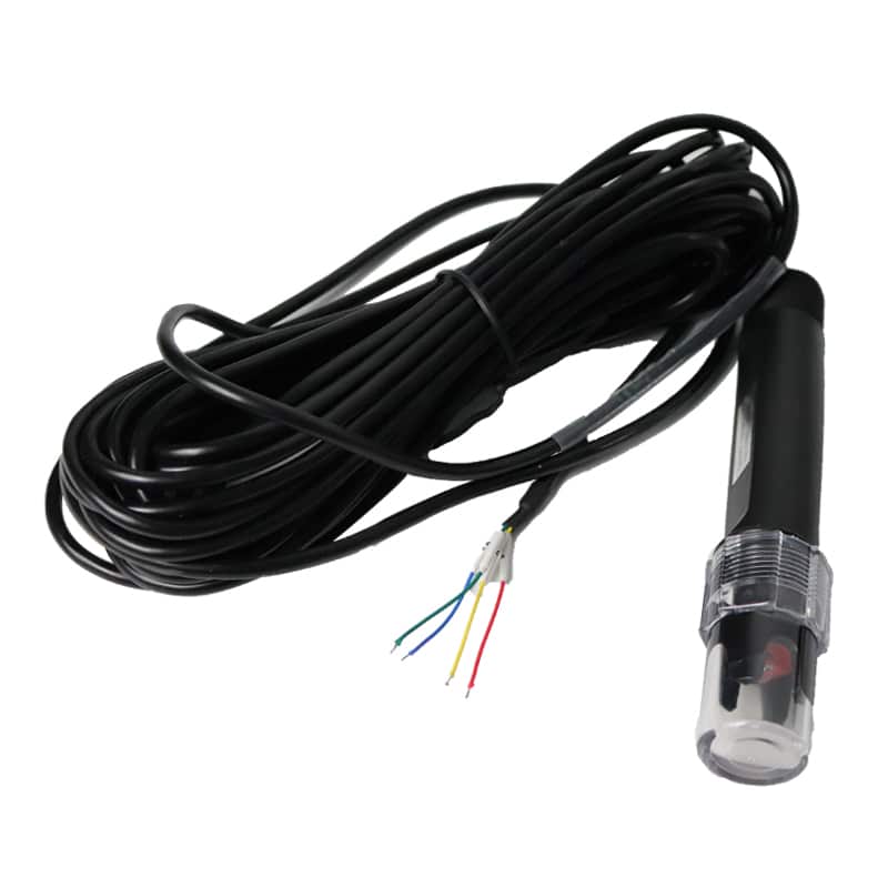
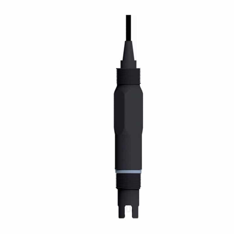
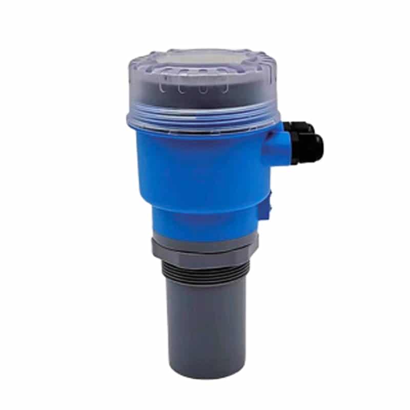
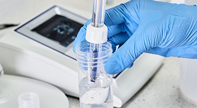
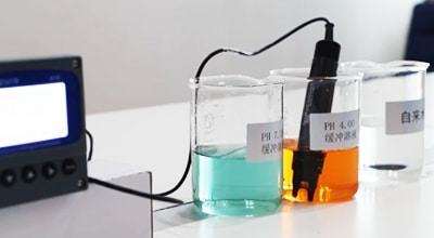
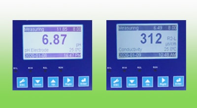
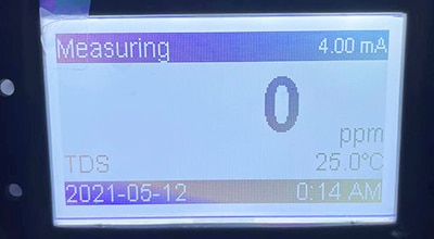
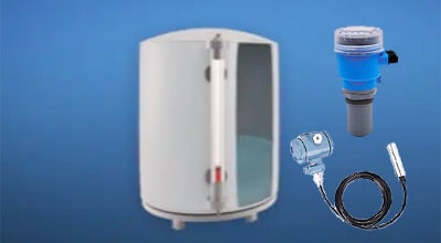
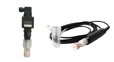
Probe illustration only: confirm the supplied probe model and technology in the quotation and manual before selecting consumables or calibration procedures.
A10 DO listed configuration
These are the listed DO system/controller values. Confirm them against the ordered version and probe documentation. The probe’s measuring limits, process limits and calibration requirements must be checked separately; do not treat the controller table as proof of compatibility with every optical or electrochemical sensor.
| Brand | Apure |
|---|---|
| Model | A10 |
| Measuring range | 0-20mg/L, automatic range switching; 0-60℃ |
| Resolution | 0.1mg/L, 0.1℃ |
| Precision | ±0.5% FS, ±0.3℃ |
| Automatic temperature compensation | 0-60℃ |
| Control interface | two sets of normally open relay contact, divided into high and low alarm signal, photoelectric isolation output |
| Signal isolation output | photoelectric coupler isolated protection 4-20mA signal output |
| Relay | arbitrary setting of hysteresis, relay load 3A 220VAC |
| Working conditions | ambient temperature of 0-60℃, relative humidity ≤ 90% |
| Output load | <300Ω (4-20mA) |
| Working voltage | 110-220V AC±10%, 50/60Hz |
| Dimensions | 96×96×115mm |
| Cut off dimensions | 91×91mm |
| Weight | 0.9Kg |
Confirm with the selected probe
- Exact probe model and optical measurement configuration.
- Input type, cable and version-specific wiring diagram.
- Temperature, pressure and salinity compensation: identify what is measured, entered manually or unsupported.
- Calibration medium, frequency, acceptance criteria and sensing-cap replacement procedure.