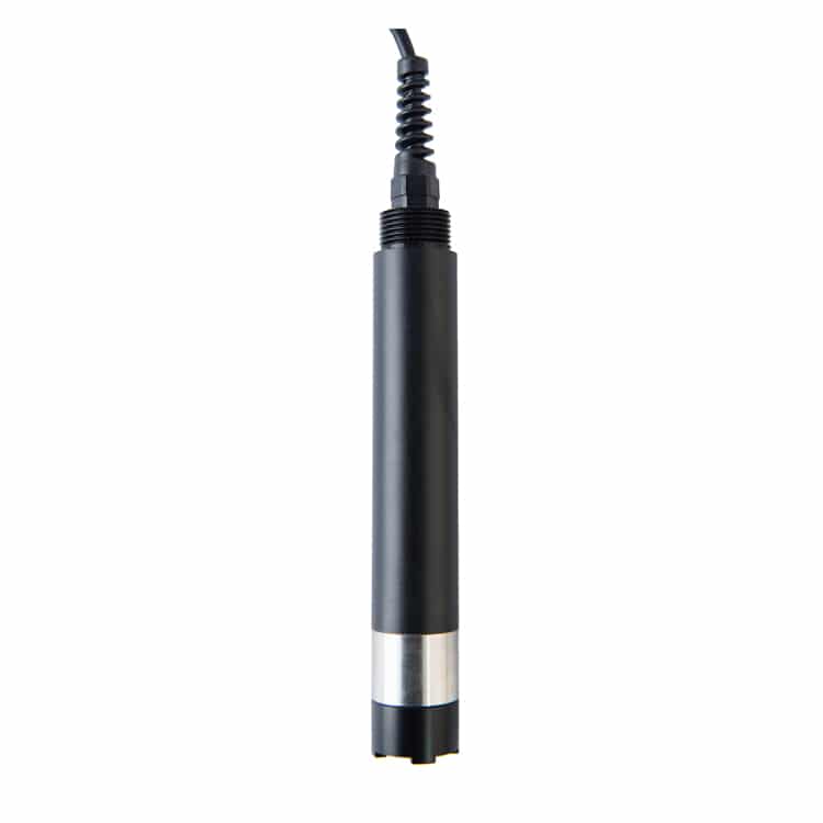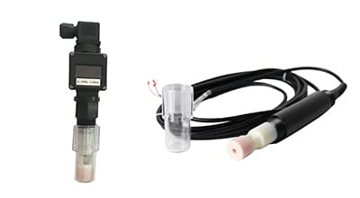
SAL Water Digital Salinity Sensor

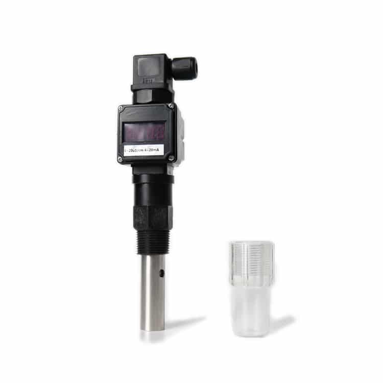
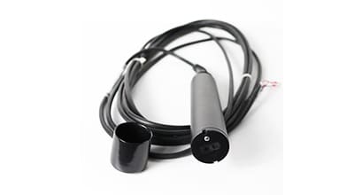
The Apure SAL-C salinity sensor is selected as part of a compatible measurement system. Confirm the salinity scale, measuring range, temperature treatment, power and signal interface before ordering. A separate display or controller must be specified when required.
- Salinity range and scale selection
- Probe/controller compatibility
- Analog or digital integration
SAL-C salinity measurement
Specify the water type and expected salinity range, including normal and upset conditions. Confirm the actual measuring principle and conversion used by the supplied sensor. When salinity is calculated from conductivity, the algorithm and temperature basis must suit the sample; estimated TDS and salinity are not interchangeable labels.
Characteristics
- Select the required sensor range and reporting units.
- Match the sensor output to the controller or data-acquisition input.
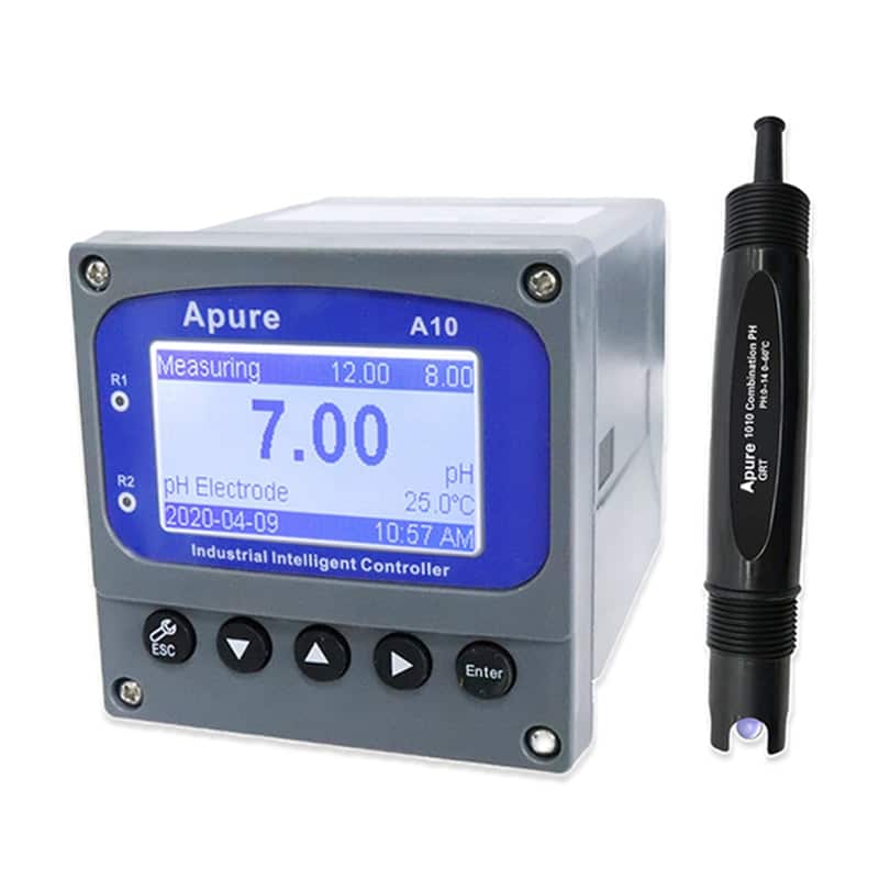
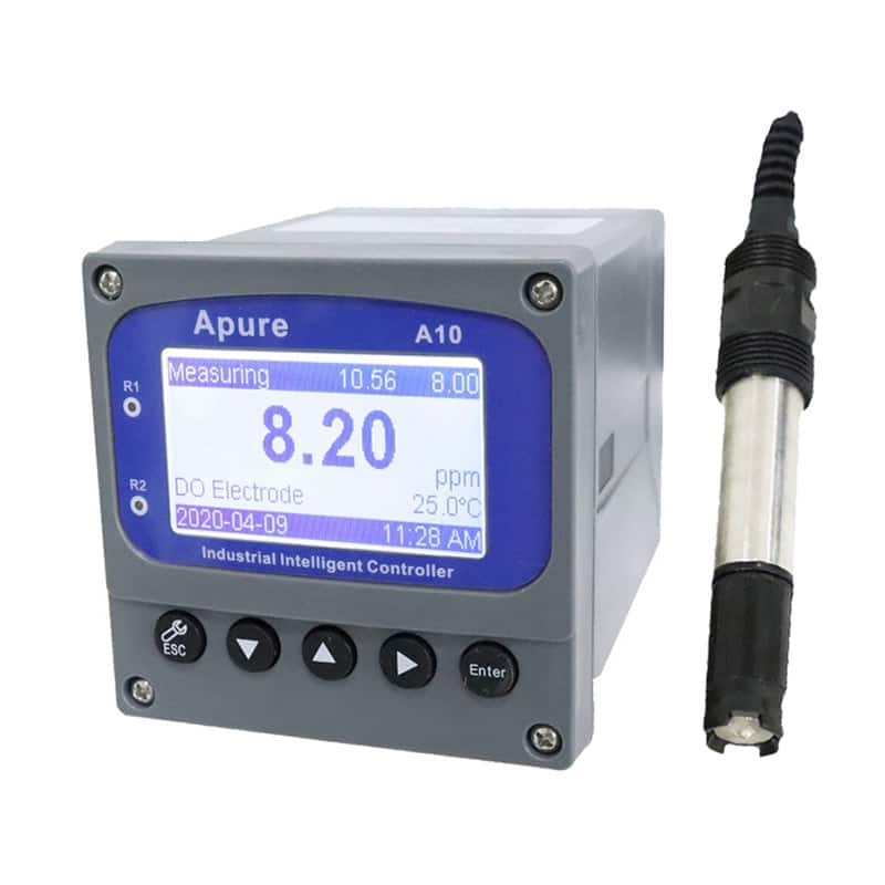
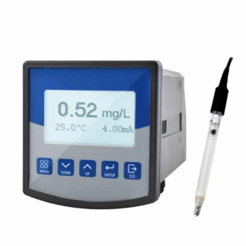
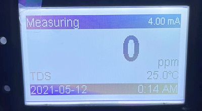
- Confirm the required display/controller separately; a screen size or control function is not a specification of every probe.
- Verify calibration and performance in the actual water matrix.
Connecting to a control system
A 4–20 mA output is an analog current signal. To record it on a computer, use a compatible isolated analog-input/data-acquisition device and configure the measurement scaling. For RS485, confirm the supplied Modbus RTU register map, baud rate, parity, address and suitable interface hardware. RS485 alone does not define the application protocol.
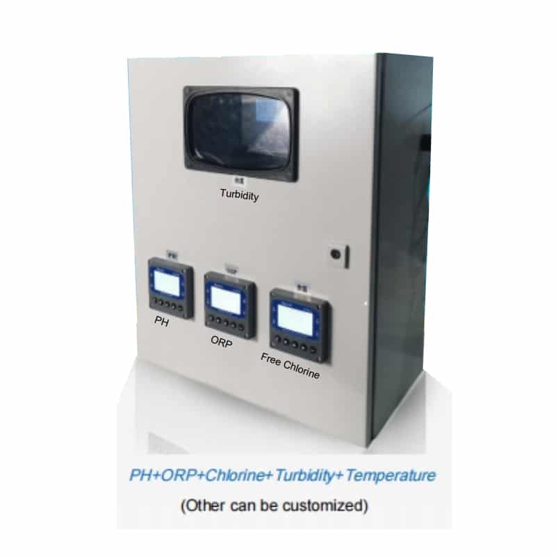
Do not assume pH or ORP measurement is included in a salinity probe. Any additional channel requires its own compatible sensor and confirmed controller configuration. Read about conductivity, salinity and measurement conditions.
SAL-C listed options and integration checks
| Item | Listed information / selection requirement |
|---|---|
| Brand / model | Apure / SAL-C |
| Listed salinity range options | 0–10, 0–100, 0–2500 or 0–100000 ppm; confirm the selected range, salinity definition and reporting basis. |
| Listed temperature range | 0–60°C; verify process limits for the supplied probe and installation. |
| Accuracy | Confirm the numerical value, whether it is % of reading or full scale, and the temperature/range conditions. |
| Resolution | Confirm salinity and temperature display increments for the selected range. |
| Temperature compensation | Confirm whether it is automatic or manual and the actual calculation/settings. |
| Signal output | Listed 4–20 mA and RS485 Modbus RTU; confirm which outputs are included and their wiring. |
| Power | Listed 12–24 VDC; follow the actual nameplate and polarity requirements. |
| Materials | PPS / ABS are listed; confirm which parts contact the liquid and their compatibility. |
Use the current probe manual, calibration instructions and system quotation to confirm the selected configuration; a controller feature list must not be substituted for sensor specifications.