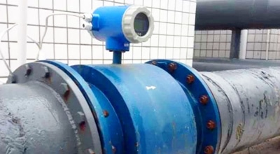
Dissolved Oxygen Meter & Sensor
A dissolved oxygen (DO) measurement describes oxygen present in water, commonly as concentration in mg/L or as percent saturation. The result is meaningful only when the reporting basis, temperature, barometric pressure, salinity, sensor condition and measurement location are understood.
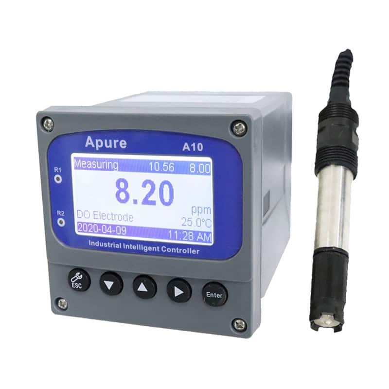
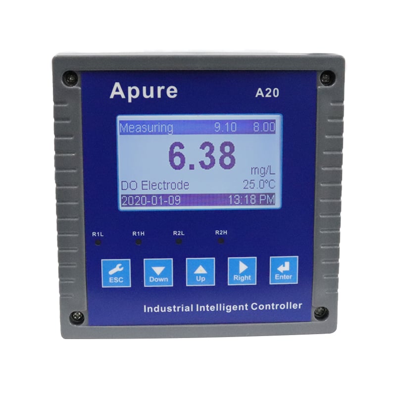
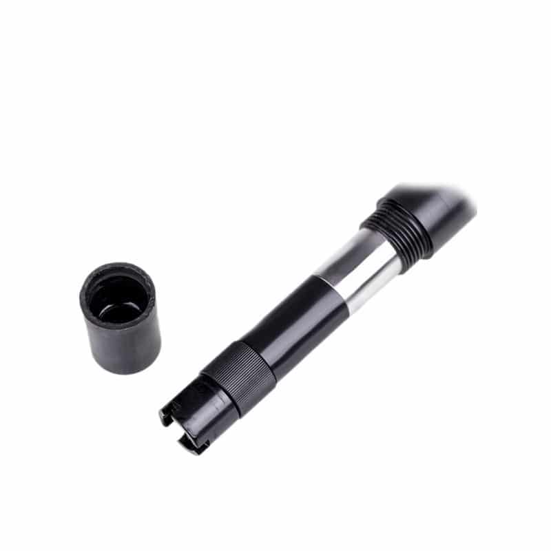
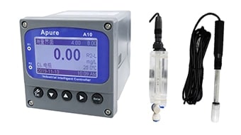
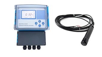
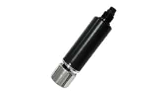
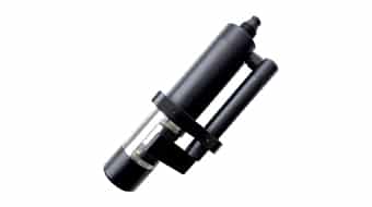
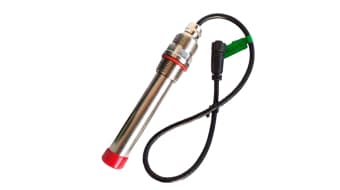
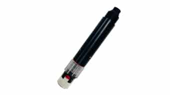
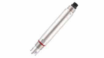
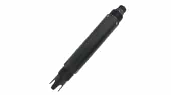
Optical, galvanic and polarographic sensors can all measure DO, but they do not use the same sensing principle or maintenance procedure. APURE currently lists the A10 and A20 optical DO meter systems, the KOG-206 optical sensor and the KOG-202S polarographic sensor. Confirm the exact sensor/controller combination and approved documentation before using a product specification or service procedure.
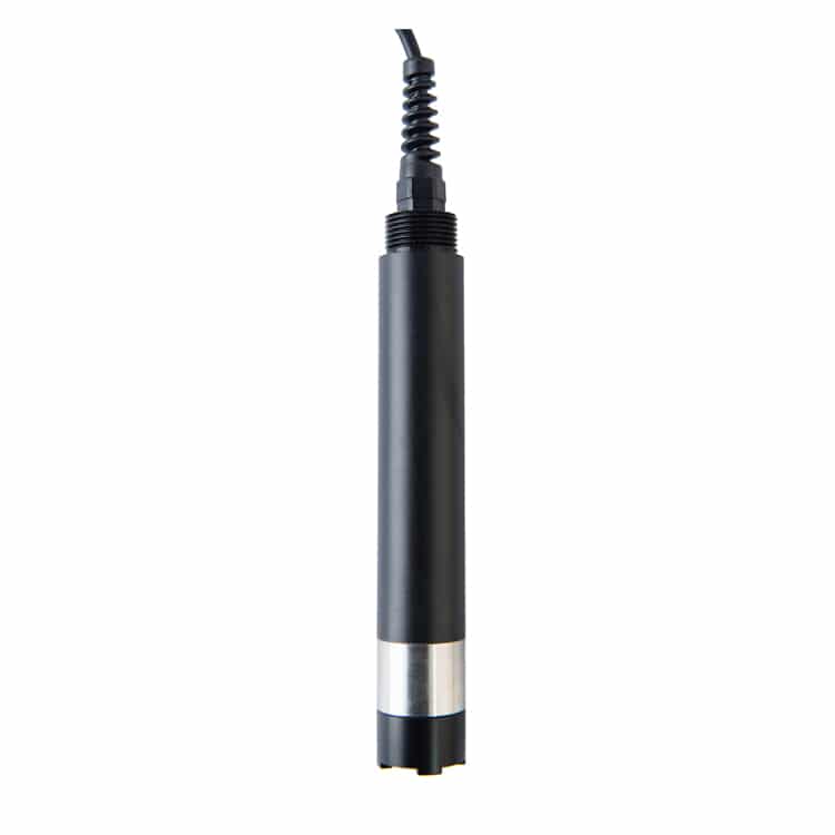
What does dissolved oxygen measure?
Dissolved oxygen measurement describes molecular oxygen, O₂, present in water. It does not count the oxygen atom chemically bound within H₂O, and it does not directly measure BOD, COD, microorganisms, pollutant identity or overall water safety.
Three related quantities must be kept distinct:
| Quantity | What it describes | Common reporting form | Important limitation |
|---|---|---|---|
| DO concentration | Oxygen mass in a volume of water | mg/L O₂ | The equilibrium concentration changes with temperature, salinity and pressure. |
| Percent saturation | The measured oxygen state relative to a defined air-equilibrium condition | % saturation | It is not a fixed conversion from mg/L. The instrument needs the applicable environmental inputs. |
| Oxygen partial pressure | The oxygen component of gas pressure that drives gas exchange and underlies many sensor responses | pressure or a sensor-derived oxygen response | It is related to concentration through equilibrium and instrument calculations; it is not identical to mg/L. |
For a fuller natural-water explanation, see What is dissolved oxygen?.
mg/L vs percent saturation: what is the difference?
mg/L reports oxygen concentration; percent saturation reports how the oxygen condition compares with equilibrium under specified conditions. A value of 100% saturation therefore does not equal one universal concentration.
Cold freshwater at higher local atmospheric pressure can have a different 100%-saturation concentration from warm, saline water at lower pressure. A meter that displays both outputs uses sensor response plus configured or measured environmental inputs to calculate them. Compare two instruments only after confirming units, temperature, salinity and pressure basis.
Can dissolved oxygen exceed 100% saturation?
Yes. Supersaturation can occur when oxygen production or gas transfer temporarily exceeds the rate at which oxygen leaves the water. Strong photosynthesis, intensive aeration, pressure changes and rapid changes in water conditions can produce readings above 100% saturation.
An unexpectedly high value should still be checked. Bubbles on the sensing surface, a probe placed directly in an aerator plume, incorrect pressure or temperature input, calibration error or a damaged sensing component can also produce a high or unrepresentative result. Confirm the physical conditions before classifying the reading as either real supersaturation or sensor error.
Why temperature, salinity and barometric pressure matter
Temperature has three different effects
- Oxygen solubility: warmer water generally holds less oxygen at air equilibrium than colder water.
- Sensor response: optical layers, membranes and electronics can respond to temperature, so the instrument may apply a sensor-specific correction.
- Actual water chemistry and biology: temperature changes biological respiration, reaction rates, stratification and process oxygen demand.
Automatic temperature compensation can correct a defined sensor calculation. It cannot reverse a real temperature-driven change in the water or substitute for salinity and pressure information.
Salinity changes the concentration relationship
Increasing salinity generally reduces equilibrium oxygen solubility. Salinity correction is therefore important when converting the oxygen response to concentration or saturation in brackish or marine water. Do not apply a freshwater assumption to seawater. Confirm whether salinity is measured, entered manually or handled outside the DO instrument.
Barometric pressure and altitude affect equilibrium
Local atmospheric pressure changes with altitude and weather. Air calibration and saturation calculations may require true local pressure rather than a weather value corrected to sea level. Confirm whether the selected instrument measures pressure, accepts a manual value or relies on a controller or external calculation.
How do optical, galvanic and polarographic DO sensors work?
Optical or luminescent DO
An optical DO sensor illuminates an oxygen-sensitive luminophore in a sensing cap or layer. Oxygen changes the luminescence response, such as its decay behavior or intensity, and the instrument relates that response to oxygen.
The optical method does not consume oxygen at a cathode and generally has low flow dependence. It also avoids electrolyte and electrochemical membrane service. The cap can still foul, age, become scratched or require replacement, and the sensor still needs temperature stability, representative water and verification.
Galvanic electrochemical DO
A galvanic sensor uses dissimilar electrode materials, electrolyte and an oxygen-permeable membrane. Oxygen crossing the membrane is reduced at the cathode, and the electrode materials provide the electrochemical driving potential. Because oxygen is consumed at the sensing surface, adequate sample movement may be required.
Galvanic does not mean maintenance-free or identical to polarographic. Membrane, electrolyte, electrode condition, temperature and the model-specific service procedure still matter.
Polarographic DO
A polarographic sensor also uses electrodes, electrolyte and an oxygen-permeable membrane, but it applies a polarization potential to support the oxygen-dependent current. After connection or service, the probe may need a model-specific polarization and stabilization period before calibration or measurement.
The membrane/electrolyte condition and sample movement affect the result. Do not assign one universal polarization time or minimum flow to every polarographic probe.
Optical vs galvanic vs polarographic DO
| Technology | Principle | Main strength | Main limitation | Maintenance | Flow sensitivity | Typical context |
|---|---|---|---|---|---|---|
| Optical/luminescent | Oxygen-dependent quenching of a sensing layer | Non-consumptive; generally lower flow dependence | Cap aging, fouling, coating damage and configuration dependence | Inspect/clean cap; verify; replace by model procedure | Low for the sensing reaction, but representative sample exchange is still required | Continuous monitoring, low-flow water and deployments where reduced membrane service is valuable |
| Galvanic | Spontaneous electrochemical cell behind a membrane | No externally applied polarization in the usual design | Oxygen consumption; membrane/electrolyte/electrode condition | Model-specific membrane, electrolyte and electrode service | May require adequate sample movement | Portable or process measurement where the service routine and flow conditions are acceptable |
| Polarographic | Applied-potential electrochemical cell behind a membrane | Established electrochemical measurement | Polarization/stabilization plus oxygen consumption | Model-specific membrane, electrolyte, electrode and startup service | May require adequate sample movement | Laboratory, portable or process systems designed for polarographic operation |
The best technology depends on the measurement objective, expected water movement, fouling, service access, deployment length, response requirement and control-system interface. One technology is not universally superior.
Why do electrochemical DO sensors need flow?
Galvanic and polarographic sensors consume oxygen at the cathode. If oxygen near the membrane is consumed faster than it is replenished, an oxygen-depleted boundary layer can form and the sensor may read low. The required movement depends on the probe and membrane design, so use the model instructions rather than a universal velocity.
Optical sensors do not consume oxygen through this reaction and normally have lower flow dependence. They still need contact with representative water. A clean optical probe in a stagnant pocket can report that pocket accurately while failing to represent the basin, pond or pipe.
Calibration and verification are different
Calibration establishes or adjusts the sensor response; verification checks whether the calibrated system performs acceptably. A calibration completed successfully in air does not prove that the installed measurement point is representative.
Use this technology-aware workflow:
- Identify the exact sensor, controller, cap or membrane and current approved procedure.
- Inspect and clean the sensing surface by the approved method.
- Complete required startup, polarization and temperature stabilization.
- Use the specified reference condition—such as water-saturated air, air-saturated water or another approved reference.
- Confirm temperature, local pressure and any required salinity setting.
- Accept calibration only after the model’s stability and diagnostic criteria are met.
- Perform a separate verification where the method or data-quality objective requires it.
- Record sensor identity, service, reference condition, environmental inputs, units and result.
A zero check or zero calibration is useful in some low-oxygen methods and instruments, but it is not automatically required for every DO sensor. Use the supplied manual and applicable measurement procedure. Do not invent one calibration interval for every deployment.
DO sensor maintenance by technology
| Technology | Maintenance item | Possible symptom | Practical check |
|---|---|---|---|
| Optical | Fouled cap/window | Slow, biased or unstable reading | Inspect and clean by the approved method; verify afterward. |
| Optical | Aged, scratched or incorrect cap | Drift, failed diagnostics or failed verification | Confirm cap identity/condition and the model replacement procedure. |
| Optical | Bubbles or poor placement | High spikes or unrepresentative trend | Change orientation/location and compare representative water. |
| Galvanic/polarographic | Damaged, loose or bubbled membrane | Drift, low response or calibration failure | Inspect membrane and internal bubbles; service by the manual. |
| Galvanic/polarographic | Electrolyte/electrode condition | Unstable zero, slow response or sensitivity loss | Inspect and service only under the model procedure. |
| Polarographic | Incomplete polarization | Drift after startup/service | Complete the specified polarization and stabilization. |
| Any | Temperature disequilibrium | Continued drift during a check | Allow sensor, reference and sample to equilibrate. |
| Any | Incorrect pressure/salinity setting | Persistent mg/L–% mismatch | Compare inputs, units and where the calculation is performed. |
What controls response time and stabilization?
DO response time depends on sensor technology, cap or membrane, temperature, oxygen step size, water movement, fouling, signal averaging and installation. A published t90 or t95 value is meaningful only with its test conditions; t90 means the time required to reach 90% of a defined step response.
Do not apply one response time to every probe. Before accepting a stable reading, confirm required startup, temperature equilibrium, flow for an oxygen-consuming probe, bubble-free contact and the instrument’s stability rule.
What can dissolved oxygen tell you?
DO can support assessment of:
- oxygen availability at the measurement point;
- aeration and oxygen-transfer performance;
- biological-process conditions and trends;
- diurnal, seasonal and depth-related changes;
- possible oxygen-demand events when interpreted with other measurements;
- corrosion, oxidation or product-quality control in a defined industrial process.
What can dissolved oxygen not determine alone?
DO alone cannot identify:
- a pollutant or its source;
- toxicity or complete ecological health;
- drinking-water or microbiological safety;
- BOD or COD concentration;
- whether nitrification is healthy;
- treatment or regulatory compliance;
- the cause of a change without supporting evidence.
A low reading can result from respiration, decomposition, stratification, poor mixing, warmer water, process load or a measurement problem. A high reading can reflect photosynthesis, aeration, pressure effects, bubbles or an input/calibration issue. Use trends and supporting parameters, then confirm the decision with the applicable reference method or authority.
How is DO used in wastewater treatment?
In activated sludge and other aerobic processes, DO supports aeration control and process diagnosis. One universal setpoint is not appropriate because oxygen demand, treatment objective, basin design, loading, temperature, solids, pH and ammonia-related conditions differ.
Place the sensor where it represents the control objective. A probe directly in an aeration plume may read the local bubble-rich condition rather than bulk mixed-liquor DO. Review multiple basin zones or depths where gradients matter, and interpret DO with load, ammonia, pH, temperature and process performance. DO can support a nitrification investigation; it does not prove nitrification health by itself.
How should DO be interpreted in aquaculture?
Aquaculture interpretation depends on species, life stage, biomass, temperature, salinity, exposure duration and system design. Do not copy one fish-safe mg/L value or saturation percentage to every pond, cage or recirculating system.
Monitor where the animals live, not only near the aerator or surface. Depth, stratification, currents and nighttime respiration can produce large differences. In ponds, the daily minimum may occur before sunrise when photosynthesis has stopped and respiration continues. Use validated alarms linked to the farm’s species and operating plan.
How should DO be interpreted in rivers, lakes and reservoirs?
Surface-water DO reflects interacting physical and biological processes. Photosynthesis can raise DO during daylight; respiration can lower it at night. Temperature, flow, wind, stratification, organic matter and mixing affect the pattern.
Low DO can support an investigation of oxygen demand or habitat condition, but it does not prove pollution or identify a pollutant. Use time series, depth profiles, flow and supporting chemistry rather than one isolated reading.
Where should a DO sensor be installed?
Choose a location that represents the process or habitat decision:
- avoid trapped bubbles and direct aerator plumes unless that local condition is the objective;
- avoid stagnant pockets that do not represent the bulk water;
- meet the model’s immersion, orientation, pressure and flow requirements;
- account for depth, stratification, tank zones and changing water level;
- provide safe access for cleaning, verification and replacement;
- protect the cable and connector under their actual ratings;
- document location, depth and mounting so future comparisons are consistent.
For commissioning and mismatch diagnostics, see Dissolved Oxygen Probe: How It Works.
How to select a DO measurement technology
| Application condition | Preferred characteristics | Why | Limitation to verify |
|---|---|---|---|
| Long-term online monitoring | Stable continuous output, manageable fouling control, accessible verification | Reduces unattended drift risk and service burden | Cap/membrane life, cleaning access, controller and logging |
| Low-flow or still water | Non-consumptive sensing or a designed flow arrangement | Avoids reaction-driven oxygen depletion at the sensing surface | Representative placement still matters |
| Wastewater aeration | Fouling tolerance, cleaning access, representative mounting, control-system integration | Supports a dependable control signal | Basin gradients, bubbles, load and maintenance history |
| Aquaculture | Suitable materials, depth/cable design, temperature/salinity handling and alarm integration | Conditions can change by depth and time | Species-specific operating criteria and redundancy |
| Low-oxygen process | Verified performance near the actual operating interval | A wide nominal range does not establish low-level performance | Detection/accuracy basis and zero/verification method |
| Portable field use | Stable checks, pressure handling, logging and clear units | Supports traceable measurements at multiple sites | Temperature equilibration and sampling consistency |
After defining these requirements, compare DO sensor technologies, calibration and selection.
APURE product evidence boundary
The current public pages identify KOG-206 as optical and KOG-202S as polarographic. A10 and A20 are presented as optical DO meter systems used with compatible probes. Exact range, accuracy, resolution, temperature element, salinity/pressure handling, flow, response time, calibration, materials, cable, output and protocol must come from the current approved documentation for the ordered sensor/controller combination.
Do not infer a specification from a product title, old blog, wiring illustration, distributor page or another APURE model. Request the current datasheet, manual, wiring diagram and quotation before final selection.
Frequently asked questions
Is DO concentration the same as percent saturation?
No. Concentration describes oxygen mass per water volume; percent saturation describes the oxygen state relative to equilibrium under specified temperature, pressure and salinity. There is no universal fixed conversion.
Does 100% saturation equal one mg/L value?
No. The equilibrium concentration changes with temperature, salinity and local pressure.
Is a reading above 100% always wrong?
No. Real supersaturation can occur. Check photosynthesis, aeration, pressure/temperature conditions and sample handling, then rule out bubbles, placement, inputs and sensor problems.
Does an optical DO sensor need flow?
The optical sensing reaction does not consume oxygen, so it generally has low flow dependence. The probe still needs representative water and freedom from fouling and trapped bubbles.
Do galvanic and polarographic sensors use the same startup?
No. A polarographic sensor uses an applied polarization potential and may require a model-specific polarization period. A typical galvanic design supplies its own electrochemical driving potential. Both can require membrane/electrolyte care and adequate sample movement.
How often should a DO sensor be calibrated?
There is no universal interval. Use the current manual, applicable method, fouling risk, deployment duration, data-quality objective and verification history.
Does low DO prove pollution?
No. Low DO can be associated with oxygen demand, respiration, stratification, temperature or poor mixing, but it does not identify the cause or pollutant. Sensor condition and placement must also be checked.
Can a DO sensor measure BOD or COD?
No. A DO sensor measures oxygen present at a point and time. BOD and COD are different method-defined measures of oxygen demand or oxidizable load.
Technical references
- USGS Chapter A6.2 — Dissolved oxygen
- USGS Use of multiparameter instruments for routine field measurements
- EPA Field Measurement of Dissolved Oxygen — LSASDPROC-106-R6 (April 23, 2025)
- ISO 17289:2014 — Optical sensor method
- ISO 5814:2012 — Electrochemical probe method
Product categories
Related articles

What is dissolved oxygen?
Dissolved Oxygen Probe How It Works?
3 Main Water Quality Parameters Types
Why is water quality important?

Main water quality indicators
About turbidity sensors
What is Turbidity?
What is ec meter?
How Does a Temperature Sensor Work?

Ozonated Water: Principles, Benefits, Applications
Distilled Water vs Purified Water: What’s The Difference?
Level Transmitter Types: Working Principles and Selection