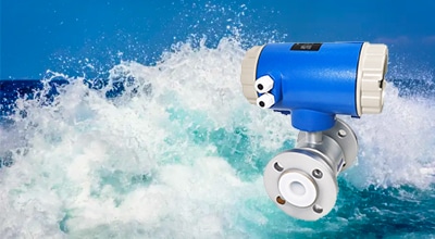
Magnetic Flow Meter
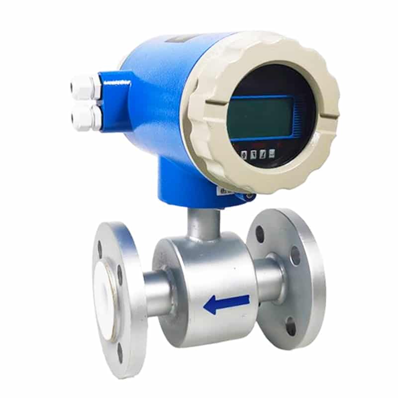
Magnetic flow meters, also known as mag meters, electromagnetic flow meter are, widely used in a variety of industrial field applications due to their reliable flow rate measurements and features such as low-pressure loss and maintenance-free operation.
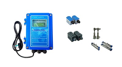
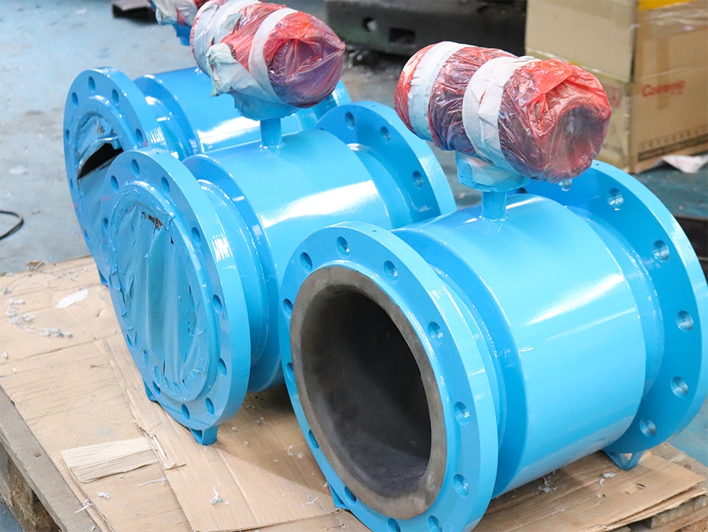
Apure’s AXT series magnetic flow meters are designed with dual-frequency excitation to achieve stable measurement, zero stability, and quick response times.
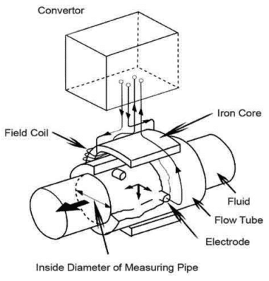
Working principle of electromagnetic flow meter
The working princple is based on Faradays Law of Electromagnetic Induction, that is, when the conductive liquid flows though the electromagnet flowmeter the duced comotive force w be produced in the conductor, and the induced elecom force is diectly poona to the velocity of conductive liquid magnetic flux density and with of conductor(inside diameter of flowmeter)
Such induced electromotive force is detected by a pair of electrodes on the tube wall of the flowmeter, and the rate of flow can be acquired by mathematical operation The quation of nduced electromotive force is as follows:
E = D · V · B
E: induced electromotive force
D: inside diameter of measuring pipe
V: velocity
B: magnetic flux density
The following conditions should be satisfied in order to obtain satisfactory measuring accuracy.
- The tested liquid shall possess the electrical conductivity
- The pipe shall be full of liquid
- The components of liquid shall be well mixed
- If the liquid has magnetic permeability, the magnetic field of the flowmeter will change, so the flowmeter shall be modified
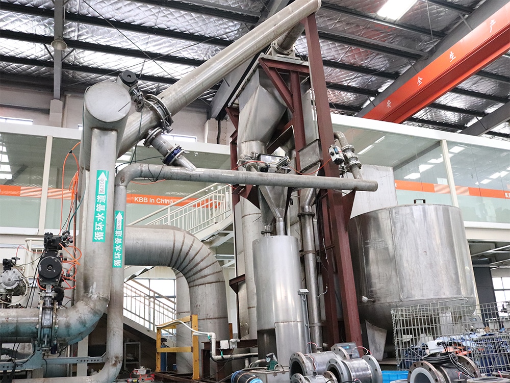
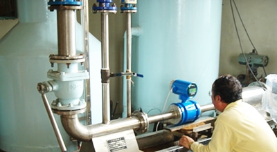
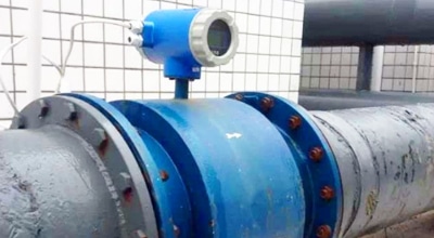
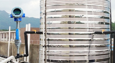
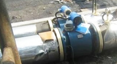
Applications
Apure as one of the leading manufacturers of electromagnetic flow meters, we produce products that are competitive in both functionality and durability. Our electromagnetic flowmeters are known for their higher performance and they can handle a variety of liquids with solid particles, such as sewage and milk. Here are some application scenarios:
- Sewage treatment plant
- Molasses
- Coal slurry
- High mineral water
- Soft drink
- Alkali and acid
- Chemical solutions
- Medicine
- Papermaking
- Petrochemical
- Metallurgical
Apure offer flowmeter solutions that address complex industrial challenges. Our flowmeter equipment has a reputation for being cost effective, easy to maintain and reliable. If you have any specific requirements, please contact us.
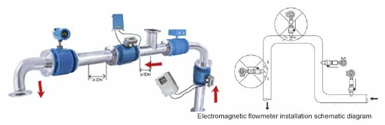
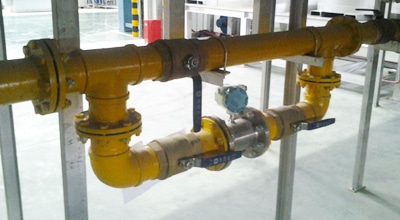
Installation of magnetic flow meter
The installation of magnetic flowmeter has an important impact on the measurement accuracy and instrument stability.
Installation environment
- Electromagnetic flowmeter should be installed in a dry, ventilated, no vibration, no strong magnetic field, no corrosive gas environment.
- Avoid direct sunlight, if necessary, should take measures to prevent sunlight.
- There should be enough space around the flowmeter for easy installation, maintenance and overhaul. ,
Pipe installation
- Electromagnetic flowmeter sensor should be installed vertically in the pipeline filled with liquid, and the fluid should flow from bottom to top.
- The sensor can not be installed in the highest position in the pipeline, so as to avoid gas accumulation affects the measurement.
- In the sensor upstream and downstream should be retained enough straight section, generally 10D ~ 15D.
- The piping connection should be firm and without leakage.
Electrical installation
- Electromagnetic flowmeter power supply should be stable and reliable AC power supply.
- The meter should be grounded to eliminate interference.
- Signal cable should be shielded and laid separately from the power line.
Electromagnetic flowmeter selection
In the selection of magnetic flow meter, the following factors should be considered:
Fluid characteristics
- Electromagnetic flowmeter can only measure conductive liquids. Therefore, in the selection should first determine whether the conductivity of the measured fluid is greater than or equal to 1μS/cm.
- Fluid viscosity, density, corrosivity and other parameters will also affect the measurement accuracy of the electromagnetic flowmeter.
Piping parameters
- The caliber of the electromagnetic flowmeter should be consistent with the caliber of the pipeline.
- In the sensor upstream and downstream should be retained enough straight section, generally 10D ~ 15D.
Measurement accuracy
Electromagnetic flowmeter measurement accuracy level is generally 0.5 level, 1.0 level, 1.5 level, 2.0 level.
Functional requirements
Some electromagnetic flowmeter also has Hart protocol, Profibus DP protocol and other functions, which can meet the communication needs of different users.
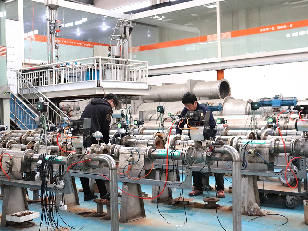
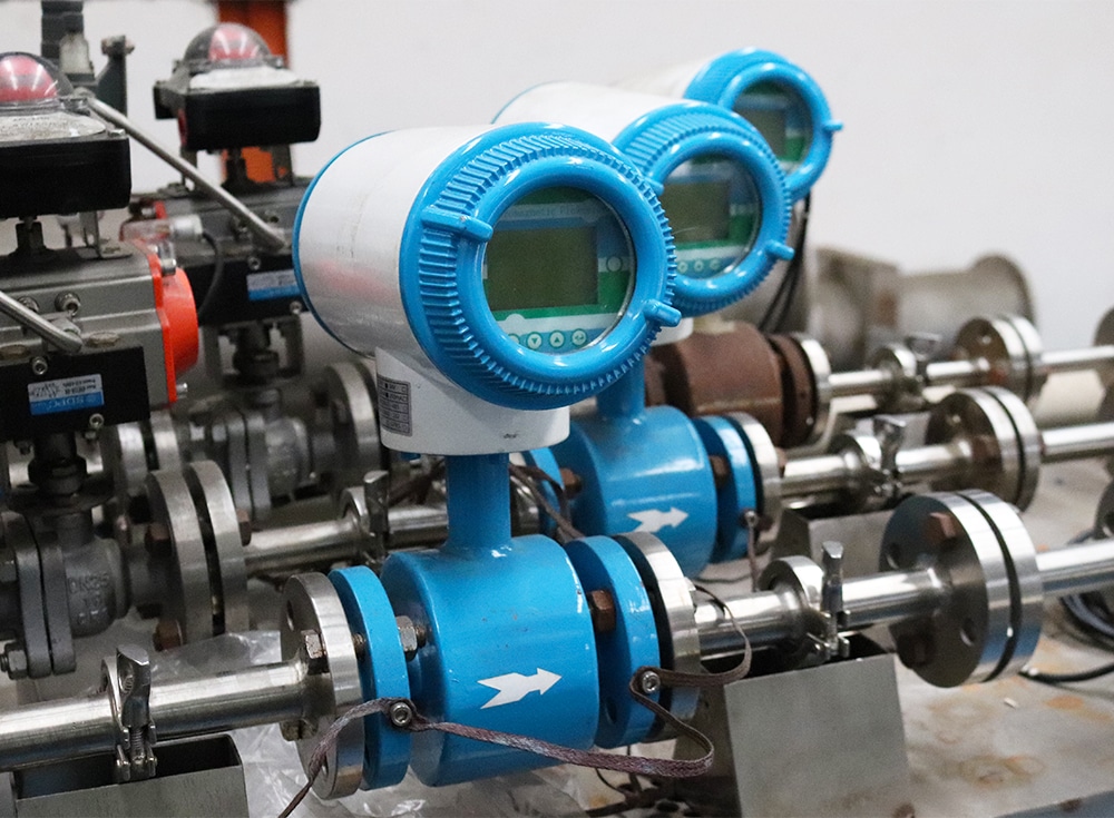
Magnetic flow meter factory
Video
FAQ
Product categories
Popular articles
Chilled water flow meter
Liquid Flow Meter
Flow meter calibration
Select the right water flow meter for you
Hot water flow meter
Sewage flowmeter

Select right irrigation flow meter
Useful information about flow units
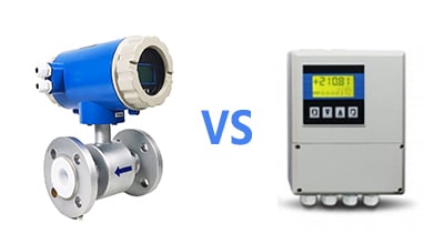
Difference between flow meter and flow transmitter
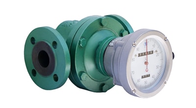
What is positive displacement flow meter?

Importance of swimming pool flow meter