
Is the flow rate in a pipe proportional to the pressure? Is flow rate related to pressure, flow rate, and pipe diameter? From the point of view of qualitative analysis, the relationship between pressure and flow rate in a pipe is proportional. That is, the higher the pressure, the higher the flow rate. The flow rate is equal to the velocity multiplied by the cross section. For any section of a pipeline, the pressure comes from only one end, i.e. the direction is unidirectional. When the outlet is closed (valve is closed), the fluid in the pipe is in a forbidden state. Once the outlet is open, its flow rate depends on the pressure in the pipe.
Pipe diameter pressure and flow
Pipe diameter refers to when the pipe wall is thin, the outer diameter of the pipe and the inner diameter of the pipe is almost the same, so the average value of the outer diameter of the pipe and the inner diameter of the pipe is taken as the diameter of the pipe. Usually refers to the general synthetic material or metal tube, when the inner diameter is larger, the average value of the inner diameter and outer diameter is taken as the tube diameter. Based on the metric system (mm), called DN (metric units).
Pressure is the internal pressure of a fluid pipe.
Flow rate is the amount of fluid flowing through the effective cross section of a closed pipe or open channel per unit of time, also known as instantaneous flow. When the amount of fluid is expressed in volume, it is called volumetric flow. When the amount of fluid is expressed in terms of mass, it is called mass flow. The volume of fluid flowing through a section of pipe per unit of time is called the volume flow rate of that section.
Relation between flow and pressure
First of all, flow rate = flow rate x pipe ID x pipe ID x π ÷ 4. Therefore, flow rate and flow rate basically know one to calculate the other parameter.
But if the pipe diameter D and the pressure P inside the pipe are known, can the flow rate be calculated?
The answer is: it is not possible to find the flow rate and the flow rate of the fluid in the pipe.
You imagine that there is a valve at the end of the pipe. When it is closed, there is a pressure P inside the pipe. the flow rate in the pipe is zero.
Therefore: the flow rate in the pipe is not determined by the pressure in the pipe, but by the pressure drop gradient along the pipe. Therefore, the length of the pipe and the differential pressure at each end of the pipe need to be indicated in order to find the flow rate and flow rate of the pipe.
If we look at it from the point of view of qualitative analysis. The relationship between the pressure in the pipe and the flow rate is proportional. That is, the higher the pressure, the higher the flow rate. The flow rate is equal to the velocity multiplied by the cross section.
For any section of the pipe, the pressure comes from only one end. That is, the direction is unidirectional. When the outlet in the direction of pressure is closed (valve closed) The liquid in the pipe is prohibited. Once the outlet is open. It flows depending on the pressure in the pipe.
For quantitative analysis, hydraulic model experiments can be used. Install a pressure gauge, flow meter or measure the flow capacity. For pressure pipe flow, it can also be calculated. The calculation steps are as follows.
- Calculate the specific resistance of the pipe S. In case of old cast iron pipes or old steel pipes. The resistivity of the pipe can be calculated by the Sheverev formula s=0.001736/d^5.3 or s=10.3n2/d^5.33.
- Determine the working head difference H = P/(ρg) at both ends of the pipe. If there is a horizontal drop h (meaning that the beginning of the pipe is higher than the end by h).
then H=P/(ρg)+h
where: H: in m.
P: is the pressure difference between the two ends of the pipe (not the pressure of a particular section).
P in Pa. - Calculate the flow rate Q: Q = (H/sL)^(1/2)
- Flow rate V = 4Q/(3.1416 * d^2)
where: Q – flow rate, m^3/s.
H – difference in head between the beginning and the end of the pipe, m.
L – the length from the beginning to the end of the pipe, m.
Flow and pressure formulas
Mention pressure and flow. I think many people will think of Bernoulli’s equation.
Daniel Bernoulli first proposed in 1726: “In a current or stream, if the velocity is low, the pressure is high. If the velocity is high, the pressure is low”. We call it “Bernoulli’s principle”.
This is the basic principle of hydrodynamics before the establishment of the equations of fluid mechanics continuous medium theory. Its essence is the conservation of fluid mechanical energy. That is: kinetic energy + gravitational potential energy + pressure potential energy = constant.
It is important to be aware of this. Because Bernoulli’s equation is deduced from the conservation of mechanical energy. Therefore, it is only applicable to ideal fluids with negligible viscosity and incompressible.
Bernoulli’s principle is usually expressed as follows.
p+1/2ρv2+ρgh=C
This equation is called Bernoulli’s equation.
where
p is the pressure at a point in the fluid.
v is the flow velocity of the fluid at that point.
ρ is the density of the fluid.
g is the acceleration of gravity.
h is the height of the point.
C is a constant.
It can also be expressed as.
p1+1/2ρv12+ρgh1=p2+1/2ρv22+ρgh2
Assumptions.
To use Bernoulli’s law, the following assumptions must be satisfied in order to use it. If the following assumptions are not fully satisfied, the solution sought is also an approximation.
Steady-state flow: In a flow system, the properties of the fluid at any point do not change with time.
Incompressible flow: the density is constant and when the fluid is a gas, the Mach number (Ma) < 0.3 applies.
Frictionless flow: the friction effect is negligible, the viscous effect is negligible.
Fluid flow along the streamline: fluid elements flow along the streamline. The flow lines do not intersect.
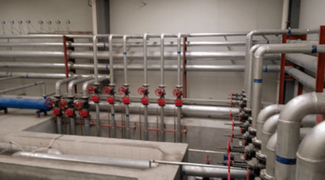
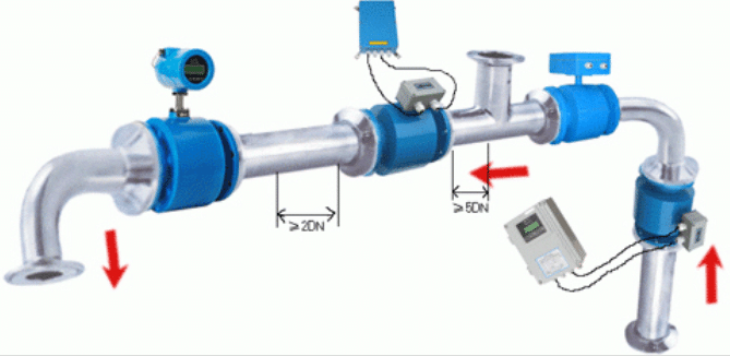
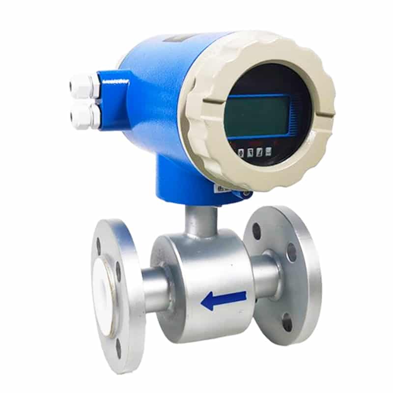
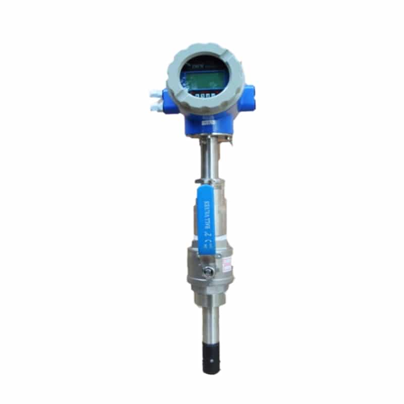
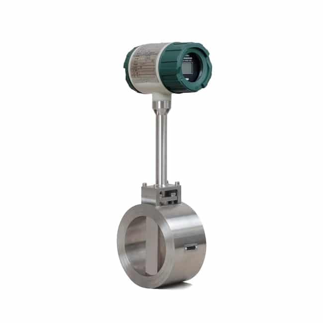
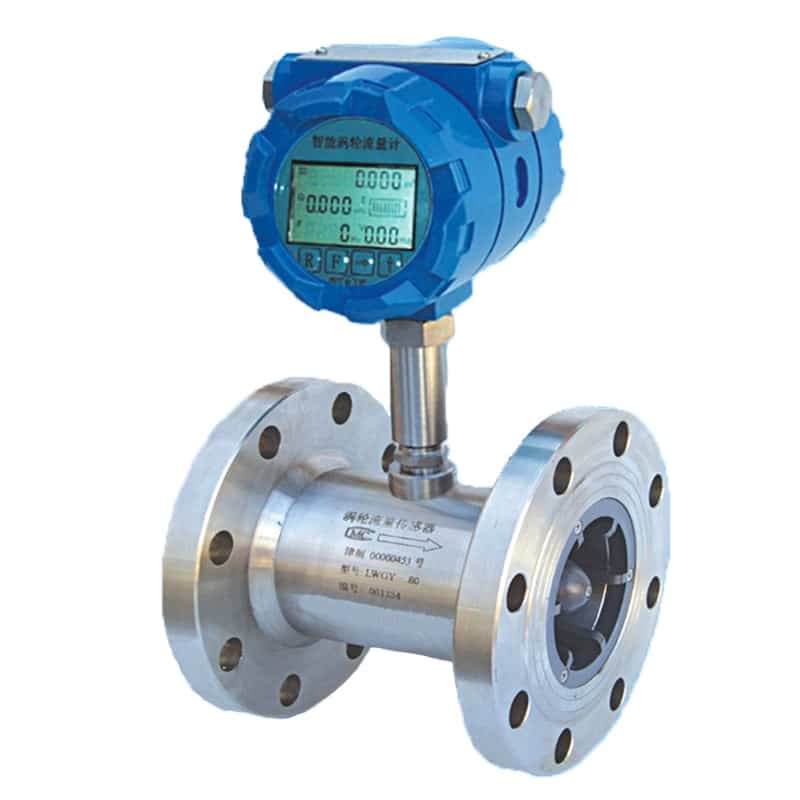
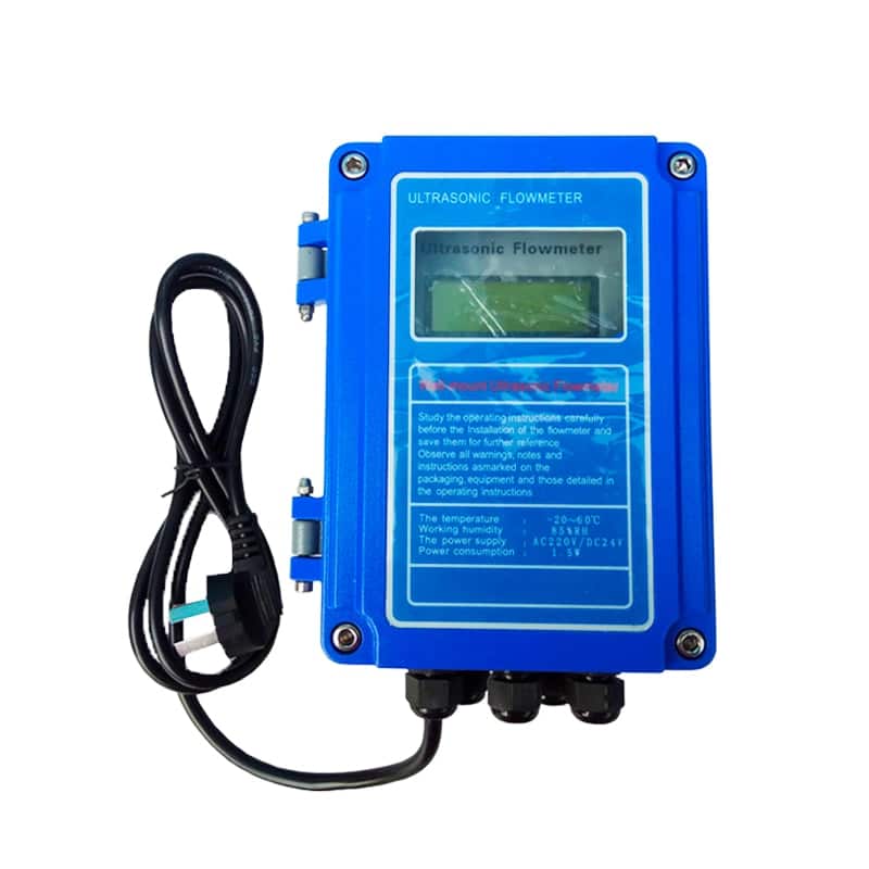
Flowmeter products

Flow and pressure calculator
Flow rate and pressure drop?
The pressure drop, also known as pressure loss, is a technical and economic indicator of the amount of energy consumed by the device. It is expressed as the total differential pressure of the fluid at the inlet and outlet of the device. Essentially, it reflects the mechanical energy consumed by the fluid passing through the dust removal device (or other devices). It is proportional to the power consumed by the respirator.
The pressure drop includes the pressure drop along the path and the local pressure drop.
Along-range pressure drop: It is the pressure loss caused by the viscosity of the fluid when it flows in a straight pipe.
Local pressure drop: refers to the liquid flow through the valve opening, elbow and other local resistance, the pressure loss caused by changes in the flow cross-section.
The reason for local pressure drop: liquid flow through the local device, the formation of dead water area or vortex area. The liquid does not participate in the mainstream of the region. It is constantly rotating. Accelerate the liquid friction or cause particle collision. Produce local energy loss.
When the liquid flows through the local device, the size and direction of the flow velocity changes dramatically. The velocity distribution pattern of each section is also constantly changing. Causes additional friction and consumes energy.
For example. If part of the flow path is restricted, the downstream pressure will drop from the restricted area. This is called pressure drop. Pressure drop is energy loss. Not only will the downstream pressure decrease, but the flow rate and velocity will also decrease.
When pressure loss occurs in a production line, the flow of circulating cooling water is reduced. This can lead to a variety of quality and production problems.
The ideal way to correct this problem is to remove the component that is causing the pressure drop. However, in most cases, the pressure drop is dealt with by increasing the pressure generated by the circulating pump and/or increasing the power of the pump itself. Such measures waste energy and incur unnecessary costs.
The flow meter is usually installed in the circulation line. In this case, the flow meter is actually equivalent to a resistance component in the circulation line. Fluid in the flow meter will produce pressure drop, resulting in a certain amount of energy consumption.
The lower the pressure drop, the less additional power is required to transport the fluid in the pipeline. The lower the energy consumption caused by the pressure drop, the lower the cost of energy metering. Conversely, the greater the energy consumption caused by the pressure drop. The higher the cost of energy measurement. Therefore, it is important to choose the right flow meter.
Extended reading: Liquid flow meter types, Select a right flow meter for irrigation
Flow rate and differential pressure?
In determining a piping system, the flow rate is related to the square root of the pressure differential. The higher the pressure difference, the higher the flow rate. If there is a regulating valve in the piping system (artificial pressure loss). That is, the effective differential pressure decreases and the flow rate becomes correspondingly smaller. The pipeline pressure loss value will also be smaller.
Extended reading: What is pressure transmitter?
Flow rate calculation from differential pressure?
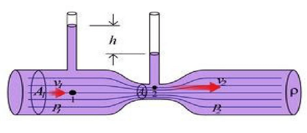
The measuring principle of differential pressure flowmeter is based on the principle of mutual conversion of mechanical energy of fluids.
The fluid flowing in the horizontal pipe has dynamic pressure energy and static pressure energy (potential energy equal).
Under certain conditions, these two forms of energy can be converted into each other, but the sum of energy remains the same.
As an example, take the volume flow equation.
Q v = CεΑ/sqr(2ΔP/(1 – β^4)/ρ1)
where: C outflow coefficient.
ε expansion coefficient
Α throttle opening cross-sectional area, M^2
ΔP differential pressure output of the throttle, Pa.
β diameter ratio
ρ1 density of the fluid under test at II, kg/m3
Qv volumetric flow rate, m3/h
According to the compensation requirements, additional temperature and pressure compensation is required. According to the calculation book, the calculation idea is based on the process parameters at 50 degrees. Calculate the flow rate at any temperature and pressure. In fact, what is important is the conversion of the density.
The calculation is as follows.
Q = 0.004714187 d^2 ε*@sqr(ΔP/ρ) Nm3/h 0C101.325kPa
That is, the volumetric flow rate at 0 degrees standard atmospheric pressure is required to be displayed on the screen.
According to the density formula.
ρ= P T50/(P50 T)* ρ50
Where: ρ, P, T indicates any temperature, pressure
The numerical values ρ50, P50, T50 indicate the process reference point at 50 degrees gauge pressure of 0.04 MPa
Combining these two formulas can be done in the program.
Extended reading: Flow meter for chilled water, Useful information about flow units,
Mass flow rate vs volumetric flow rate