
The conductivity cell constant converts measured conductance into conductivity. For an ideal parallel-electrode cell, the geometric relationship is K = d/A, where d is the spacing between electrodes and A is their effective area. Conductivity is then κ = K × G = K/R. Real cells are calibrated because field geometry, electrode surface condition and construction affect the effective constant.
A cell design and nominal constant are selected for the expected conductivity range, sample chemistry, temperature, fouling risk and required accuracy. Lower-conductivity measurements generally need a geometry that provides adequate conductance and careful control of contamination and temperature; more conductive samples may require a different geometry to avoid polarization or range limitations. See the Conductivity and TDS hub for the broader measurement context.
Conductivity Sensor Working Principle
In a contacting conductivity cell, the instrument applies an alternating electrical signal to limit electrode polarization and measures conductance through the sample. Conductance depends on the combined ionic composition and the cell geometry. Applying the calibrated cell constant converts conductance to conductivity; the result does not identify individual ions or directly determine TDS.
κ=K×G
- κ = conductivity (S/cm or μS/cm)
- G = measured conductance
- K = cell constant
Two Common Types of Conductivity Sensors
| Typology | Rationale | Specificities |
| Contact type (electrode type) | Two electrodes are immersed in water, an AC voltage is applied, and the current through the water is measured to calculate conductivity. | High accuracy for low to medium concentration liquids |
| Inductive (electromagnetic induction) | Electromagnetic field generated by a coil induces an electric current caused by the flow of ions in water (no electrodes in direct contact with the liquid) | Strong anti-pollution ability, suitable for high concentration of corrosive liquids |
Types of Conductivity Sensors
What Is The Conductivity Cell Constant?
The conductivity cell constant, abbreviated “K-value”, is the ratio of the distance between the conductivity electrodes to their effective area in cm-¹. It determines the range and accuracy of conductivity measurements for a given configuration. It determines the range and accuracy of conductivity measurements of an electrode in a particular configuration.
The formula is expressed as:
K = d / A
- d is the distance between the two electrodes (in cm)
- A is the effective area of the electrode (in cm²)
This means: Without an accurate conductivity cell constant, a true and reliable conductivity value cannot be obtained.
Battery Constants And Application Range
| Cell constant K value (cm-¹) | Applicable Liquid Type | Application Examples |
| 0.01 | Ultrapure water, water for injection | Electronics, pharmaceutical industry |
| 0.1 | Deionized water, drinking water | Waterworks, reverse osmosis systems |
| 1.0 | General industrial wastewater, recycled cooling water | Plating, chemical, air-conditioning systems |
| 10.0 | High concentration electrolyte, strong acid and alkali | Battery fluid, pickling solution, concentrated salt water, etc. |
Table of Battery Constants And Application Range
Temperature Effect
The migration rate of ions in water is very much affected by temperature, and as the temperature rises, the conductivity usually rises as well.
- The general rule is that for every 1°C rise in temperature, the conductivity rises by about 2~3%.
- Solution: Conductivity probes usually have a built-in temperature sensor and automatic temperature compensation (ATC) on the instrument side to correct to a reference temperature (usually 25°C).
Polarization Effect
When voltage is applied to the electrode, ions accumulate on the surface of the electrode to form a “double layer”, which prevents the flow of current and leads to low measurements. Polarization is more severe with low-frequency voltage or direct current stimulation.
Countermeasures:
- Use high-frequency AC excitation (e.g., 1 kHz to 10 kHz) to avoid polarization;
- Platinize the electrodes or use a four-electrode probe technique to eliminate the effect.
Platinization
It is the plating of a metal electrode (usually platinum or stainless steel) with a porous and rough layer of platinum black.
Increase electrode surface area and reduce current density; reduce polarization effect; improve signal stability and lifetime. Suitable for two-electrode probes, especially effective in measuring low conductivity or high precision requirements.
How Do Four-Cell Conductivity Probes Eliminate Polarization And Contact Coating Effects?
Two pairs of electrodes, one pair for applying current (current pole) and one pair for detecting voltage (voltage pole)
| Issue Type | How Four-Electrode Probes Respond |
|---|---|
| Polarization Effect | Voltage-sensing electrodes carry no current, so no polarization potential is formed. |
| Electrode Fouling/Scaling | Uses differential measurement + low excitation current to minimize contact resistance interference. |
| Signal Stability | Measurements are less sensitive to fouling or electrode aging, resulting in lower maintenance needs. |
How to choose a conductivity cell constant
Start with the expected minimum and maximum conductivity and the meter or transmitter input range. Then consider electrode material, two- or four-electrode geometry, sample compatibility, temperature measurement, installation, flow, fouling and calibration access. The meter and sensor must use the same effective cell constant, whether it is entered manually or recognized by the instrument.
There is no universal cell constant that is correct for every application. Confirm the supported range and calibration procedure from a reconciled instrument datasheet before specifying a model. Model-level cell constants are intentionally not reproduced here because the current product specifications require separate reconciliation.
Choice of Conductivity Cell Design: 2 Cells or 4 Cells?
A conductivity meter is the most accurate method of measuring the conductivity of a solution. Most conductivity meters use a two-electrode cell, usually made of platinum, but some electrodes are made of titanium, gold-plated nickel, or graphite. Some conductivity probes use a four-electrode cell.
| Comparison Item | 2-Electrode (2-Cell) | 4-Electrode (4-Cell) |
|---|---|---|
| Anti-Polarization Ability | Moderate — prone to ion buildup and polarization, resulting in measurement errors | High — voltage electrodes carry no current, not easily polarized |
| Measurement Stability | Sensitive to water quality; easily affected by fouling or scaling | High stability, stronger resistance to fouling |
| Applicable Conductivity Range | Suitable for low to medium conductivity liquids (e.g., pure water, RO water) | Suitable for high-conductivity liquids (e.g., acids, brine, industrial wastewater) |
| Maintenance Frequency | Requires regular cleaning due to contamination or scaling | Low maintenance, not easily fouled |
| Structural Cost | Simple design, lower manufacturing cost | More complex design, slightly higher cost |
| Typical Applications | Laboratory testing, drinking water, pure water monitoring | Industrial sites, wastewater discharge, high-concentration chemicals, corrosive fluids |
Conductivity Cell Design Selection Chart
Select contacting-cell geometry only from a verified, application-specific instrument and sensor datasheet. Do not infer compatibility or performance from a generic two- versus four-electrode comparison.
Summary
Although the conductivity cell constant is small, it is the “big contributor” behind the accurate water quality monitoring. Choosing the right sensor structure and matching the reliable instrumentation system is the only way to realize accurate data and stable equipment.
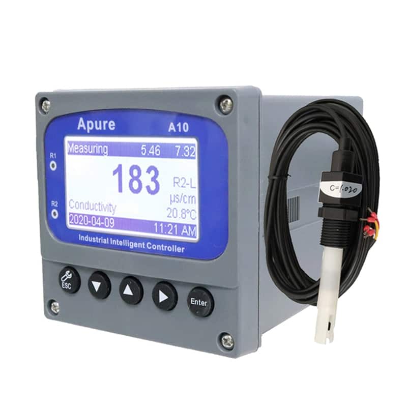
At Apure, we understand that water quality monitoring is about more than just data – it’s about accuracy, reliability and long-term system performance. Whether you’re dealing with ultrapure water, industrial wastewater, or critical process applications, our conductivity sensors and instruments deliver results you can trust. Find out more about how Apure can support your water monitoring needs, or contact our team for tailored advice.
Technical references
Cell selection, calibration and conductivity reporting are supported by ASTM D1125-23, ISO 7888 and the USGS specific-conductance measurement guidance. Related pages explain how a conductivity meter works and the conductivity–resistivity relationship.