
In the field of fluid measurement, electromagnetic flow meters stand out as reliable and accurate devices for measuring the flow of electrically conductive fluids. From water management systems to industrial processes, electromagnetic flow meters play a vital role.
Electromagnetic flowmeter introduction
Electromagnetic flowmeter plays a vital role in the field of fluid measurement, its use and importance is mainly reflected in the following aspects:
- Accurate measurement of conductive fluid flow: Electromagnetic flow meters are devices that can accurately measure the flow of conductive fluids (e.g. water, acid and alkali solutions, etc.). Its operating principle based on electromagnetic induction allows it to provide highly accurate flow data, whether in water treatment plants, industrial production or other fluid management scenarios.
- Unaffected by the nature of the fluid: In contrast to some other types of flow meters, the electromagnetic flow meter is insensitive to changes in the density, viscosity, temperature and pressure of the fluid. This allows it to maintain high measurement accuracy when handling a wide range of fluids, making it suitable for diverse industrial applications.
- Suitable for corrosive and dirty liquids: Since the sensors of electromagnetic flow meters have no direct contact with the fluid, they are highly resistant to corrosive liquids and liquids with particles or contaminants. This makes it excellent in environments where chemicals, wastewater, etc. are handled.
- Widely used in industrial process control: Electromagnetic flow meters are used in industrial production to monitor and control fluid flow, for example in the chemical, pharmaceutical and food processing industries. Their highly accurate measurement data helps to optimize processes and increase productivity.
- Low maintenance and long service life: Since there are no moving parts inside an electromagnetic flowmeter that are in direct contact with the fluid, they have lower maintenance requirements and a longer service life than some mechanical flowmeters.
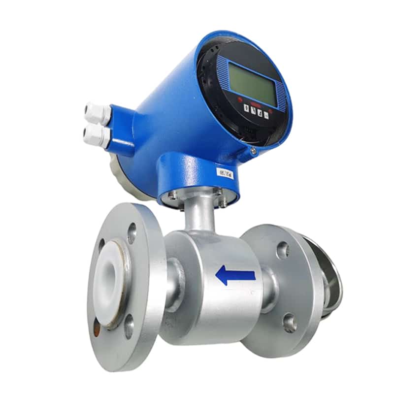
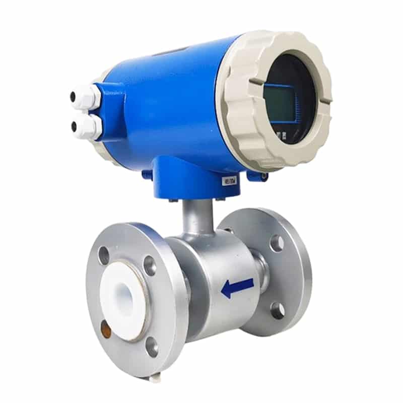
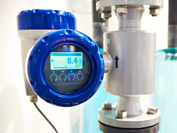
Apure’s AYT Digital Liquid Magnetic Flow Meter features fast response and elimination of output noise, and its design and quality control system ensures high accuracy and reliability, it is an excellent choice.
Next, the working principle of the electromagnetic flow meter and the theoretical basis for its use will be explained.
Faraday’s law and magnetic field generation
Overview of Faraday’s Law of Electromagnetic Induction
Faraday’s Law of Electromagnetic Induction was formulated by the British scientist Michael Faraday in 1831, and describes the effect of a changing magnetic field on the current induced in a conductor. The law shows that when the magnetic field changes with respect to a conductor, an electric potential is induced in the conductor. This provided a solid theoretical basis for the phenomenon of electromagnetic induction.
Application of the law to electromagnetic flowmeters
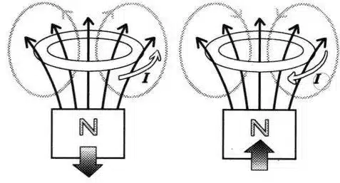
In electromagnetic flowmeters, Faraday’s law of electromagnetic induction is applied by generating a magnetic field around the pipe in which the fluid is located.
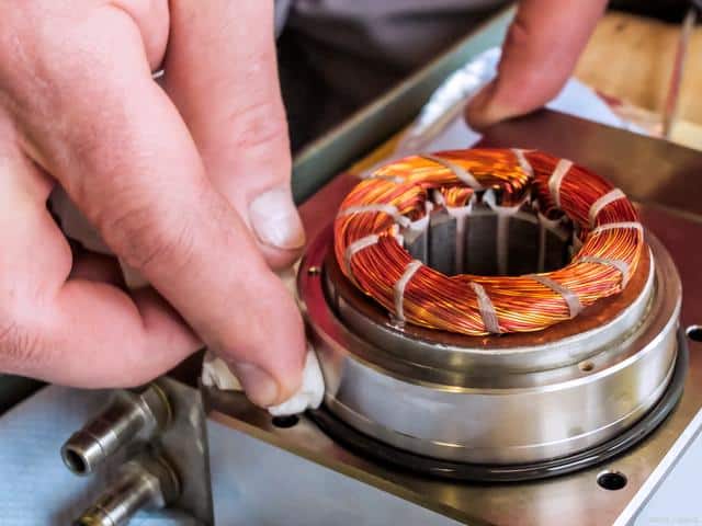
- The role of coils or electrodes:
Inside an electromagnetic flow meter, there are usually two coils or electrodes that are located on opposite sides of the pipe. These two coils are energized to create a uniform magnetic field around the fluid.
- Variable magnetic field:
When an electrically conductive fluid passes through this magnetic field, it cuts through the magnetic flux lines, causing the magnetic field to change in the pipe. This changing magnetic field is the key to applying Faraday’s law of electromagnetic induction.
- Generation of induced electromotive force:
Due to the changing magnetic field, an electric potential is induced inside the conductor according to Faraday’s law of electromagnetic induction. In an electromagnetic flowmeter, the fluid is the conductor, so an induced electromotive force is induced in the fluid.
Purpose of magnetic field generation
The purpose of generating a magnetic field in an electromagnetic flowmeter is to utilize the induced electromotive force to obtain information related to the fluid flow rate. This is accomplished by measuring the magnitude and frequency of the induced electromotive force.
- Proportional to the flow rate:
The magnitude of the induced electromotive force is directly proportional to the average flow rate of the fluid. Therefore, by measuring the induced electromotive force, the flow rate of the fluid can be deduced.
- Measurement of key parameters:
The sensor (usually the electrode) of an electromagnetic flowmeter measures the voltage caused by the induced electromotive force, and this voltage value is the key parameter for the subsequent calculation of the flow rate.
Interaction of fluids with magnetic fields
Interaction of a conductive fluid with a magnetic field
The key to an electromagnetic flow meter is the interaction of an electrically conductive fluid with a magnetic field. When a conductive fluid, such as water or a solution, flows through a pipe with a magnetic field, an important interaction occurs between it and the magnetic field.
- Effect of magnetic field:
The presence of a magnetic field exerts a force on the charged particles (electrolytes) in the fluid. The direction of this force is related to the direction of motion of the fluid, the direction of the magnetic field, and the positive or negative charge.
- Lorentz force:
This interaction results in the Lorentz force, the magnitude of which is related to factors such as current density, magnetic induction, and the velocity of the fluid.
Generation of inductive electromotive force
The Lorentz force acts to create an induced electromotive force in a conductive fluid, which is the basis for the operation of an electromagnetic flow meter.
- Cutting through magnetic flux lines:
When a conductive fluid passes through a magnetic field, due to the motion of the fluid, it cuts through the magnetic flux lines, causing a change in the magnetic field.
- Faraday’s Law of Electromagnetic Induction:
According to Faraday’s Law of Electromagnetic Induction, a change in the magnetic field induces an electric potential in a conductor. In an electromagnetic flow meter, a conductive fluid acts as a conductor and therefore induces an electric potential in the fluid.
- The induced electromotive force is proportional to the flow rate:
The magnitude of the induced electromotive force is directly proportional to the flow rate of the fluid. The faster the fluid flows, the greater the induced electromotive force.
The role of electrodes
In order to measure the induced electromotive force, electrodes or sensors are usually installed inside the electromagnetic flowmeter, which are in contact with the fluid.
- Detection of induced electromotive force:
The electrodes detect a voltage signal caused by an induced electromotive force. This voltage signal varies with the fluid flow rate, thus providing information about the flow rate.
- Measuring the flow rate in real time:
By measuring the voltage signal in real time, the electromagnetic flowmeter is able to accurately calculate the flow rate of the fluid, thus realizing real-time monitoring and control of the flow rate.
Voltage sensing and measurement
The process of induced voltage generation
The induced voltage is a key parameter in electromagnetic flowmeters, and its generation process is closely related to the Lorentz force and Faraday’s law of electromagnetic induction caused by the passage of fluid through a magnetic field.
- The effect of the Lorentz force:
When an electrically conductive fluid passes through a magnetic field, the Lorentz force causes a charge in the fluid to move, which in turn induces an electric current in the fluid.
- Current-induced change in magnetic field:
This current-induced change in the magnetic field produces an induced electromotive force, or induced voltage, in the conductor. The magnitude of this voltage is related to the Lorentz force, the flow rate, and the strength of the magnetic field.
The role of electrodes or sensors
To measure this induced voltage, electromagnetic flowmeters are usually equipped with electrodes or sensors that are in direct contact with the fluid and are used to detect the voltage caused by the current.
- Installation of electrodes:
Electrodes are usually mounted on the inside wall of the pipe through which the fluid passes, allowing them to come into direct contact with the fluid. These electrodes are usually found in pairs, on each side of the pipe.
- The electrodes are electrically connected to the fluid:
The electrodes transmit a detected voltage signal through a cable to the measurement system of the electromagnetic flowmeter. This voltage signal is caused by an electric potential induced in the fluid, the magnitude and frequency of which is proportional to the flow rate of the fluid.
Measurement methods
Electromagnetic flow meters measure the induced voltage by means of electrodes or sensors and calculate the flow rate of the fluid by the following steps.
- Amplifying and conditioning voltage signals:
The measurement system of an electromagnetic flowmeter usually includes circuitry to amplify and condition the voltage signal obtained from the electrodes to ensure signal stability and accuracy.
- Calculate flow rate:
From the measured voltage signal, the flow meter’s electronic system calculates the flow rate of the fluid. This calculation is based on the strength of the magnetic field, the distance between the electrodes and the properties of the conductive fluid.
- Output display and data transmission:
The calculated flow rate information can be displayed on the device through outputs or transmitted to devices such as control systems or recorders for real-time monitoring and recording.
Flow rate calculation and output display
The induced voltage is used to calculate the flow rate
- The flow rate is proportional to the induced voltage:
The magnitude of the induced voltage is directly proportional to the velocity of the fluid flowing through the magnetic field. This is because the induced voltage is caused by a combination of the Lorentz force and Faraday’s law of electromagnetic induction, and these in turn are directly related to the velocity of the fluid.
- Calculations based on the laws and physical relationships:
The measurement system of an electromagnetic flowmeter uses the magnitude and frequency of the induced voltage, combined with physical parameters such as magnetic field strength, distance between electrodes, etc., to derive the actual flow rate of the fluid through a series of mathematical calculations.
- Real-time nature of the calculations:
These calculations are performed in real time, so the electromagnetic flowmeter is able to provide accurate, real-time flow rate information for application scenarios that require a rapid response to changes in flow rate.
The output mechanism presents flow rate information
- Local display:
Electromagnetic flowmeters are usually equipped with a local display for instantaneous display of measured flow rate information. Such a display is usually presented in digital or graphical form, providing a user-friendly interface.
- Analog signal output:
Electromagnetic flowmeters can also transmit flow rate information to control systems or other devices through analog signal outputs. This helps to automate process control.
- Digital communication protocols:
Some advanced electromagnetic flowmeters support digital communication protocols, such as MODBUS or HART, through which flow rate information can be transmitted to a monitoring system or an upper level control system.
- Data logging and analysis:
Flow rate information can also be logged to a data storage device for subsequent analysis and review. This aids in monitoring fluid system performance trends and troubleshooting.
- Alarms and warning systems:
Some electromagnetic flowmeters are equipped with an alarm system that alerts the operator to make necessary adjustments and maintenance when the flow rate is outside the set range.
Electromagnetic flowmeter calibration and installation
Installing an electromagnetic flow meter requires selecting a suitable location, ensuring that it is installed in a straight pipe and avoiding interference, then preparing the piping, tools and materials for proper installation and connection to the piping and control system according to the manufacturer’s guidelines.
Calibrating an electromagnetic flowmeter involves confirming its specification and operating condition, then carrying out zero and range calibration in accordance with the manufacturer’s manual, firstly adjusting the output to zero with no flow, then calibrating the output using a standard flow rate value to ensure that it matches the standard value, and finally verifying and documenting the results of the calibration and checking and recalibrating it at regular intervals to ensure that the measurements are accurate.

Typical application scenarios for electromagnetic flow
Industrial process control
- Chemical and pharmaceutical industry: Monitor the flow of chemicals, solutions or liquid pharmaceuticals for process control and dosing.
- Food and beverage production: Measure the flow of liquid foodstuffs (e.g. fruit juices, milk, etc.) to ensure that the production line is running correctly and to control dosage ratios.
- Manufacturing: Used in flow monitoring of fluids such as lubricants, coolants, hydraulic fluids, etc.
Water treatment and supply
- Water supply systems: Used to monitor the flow of water in municipal water supply systems, monitoring supply and flow rates in real time.
- Wastewater treatment: Measures and monitors the flow of effluent in wastewater treatment plants, helping to control the treatment process and ensure environmental compliance.
Energy industry
- Oil & gas: Measure the flow of oil, gas or water during pipeline transportation for pipeline monitoring and metering.
- Power plants: Measure the flow of cooling water, circulating fluids, etc. to help manage the operation and maintenance of power generation equipment.
HVAC (heating, ventilation and air conditioning) systems
- Buildings and industrial facilities: Used to monitor the flow of water in heating and air conditioning systems to regulate temperature and control energy consumption.
Special applications
- Mining and metals smelting: Monitoring the flow of liquid metals or slurries for production process control.
- Marine engineering: Used in marine resource development and marine scientific research for the measurement of ocean currents.
Summary
Overall, electromagnetic flowmeters operate on the Faraday’s Law of Electromagnetic Induction, demonstrating their ability to accurately measure the flow of electrically conductive fluids, which, combined with their low maintenance requirements, makes them an indispensable tool in a variety of fields.
Apure offers instruments for water quality analysis, flow meters, level measurement, pressure measurement, temperature measurement, ozone generators and more. Feel free to contact us.