Magnetic Flow Meter

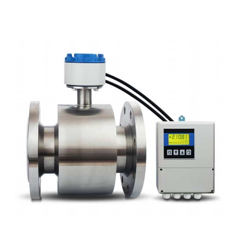
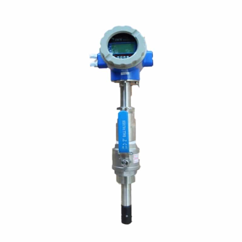
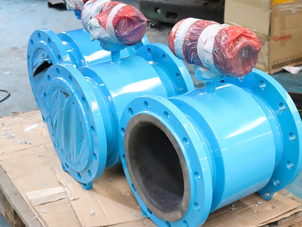
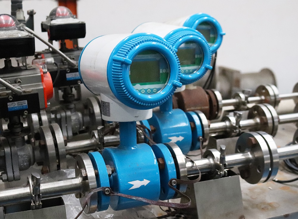
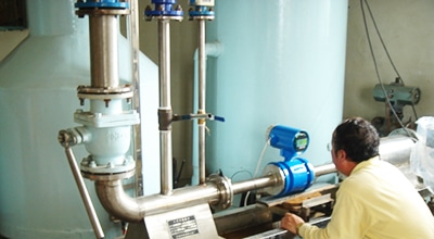
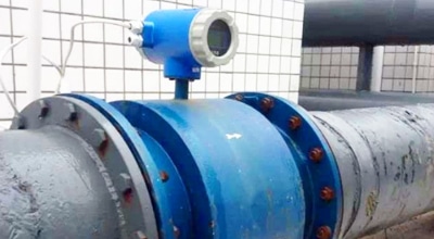
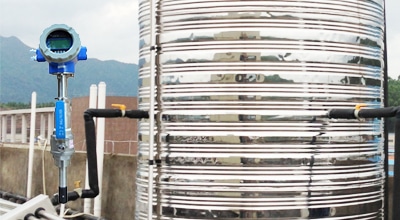
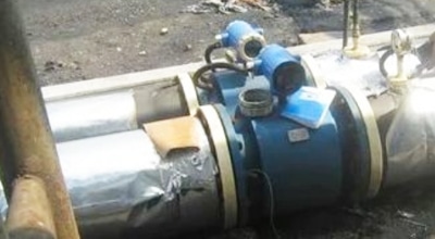
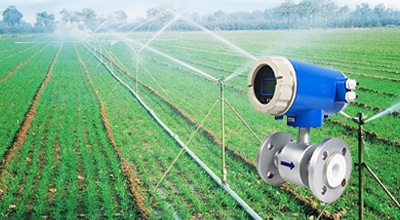
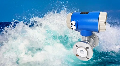
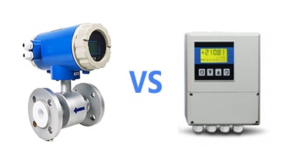
Magnetic flow meters, also known as mag meters, electromagnetic flow meter are, widely used in a variety of industrial field applications due to their reliable flow rate measurements and features such as low-pressure loss and maintenance-free operation.

Apure’s AXT series magnetic flow meters are designed with dual-frequency excitation to achieve stable measurement, zero stability, and quick response times.

Working principle of electromagnetic flow meter

The working princple is based on Faradays Law of Electromagnetic Induction, that is, when the conductive liquid flows though the electromagnet flowmeter the duced comotive force w be produced in the conductor, and the induced elecom force is diectly poona to the velocity of conductive liquid magnetic flux density and with of conductor(inside diameter of flowmeter)

Such induced electromotive force is detected by a pair of electrodes on the tube wall of the flowmeter, and the rate of flow can be acquired by mathematical operation The quation of nduced electromotive force is as follows:

E = D · V · B

E: induced electromotive force
D: inside diameter of measuring pipe
V: velocity
B: magnetic flux density


The following conditions should be satisfied in order to obtain satisfactory measuring accuracy.

  1. The tested liquid shall possess the electrical conductivity
  2. The pipe shall be full of liquid
  3. The components of liquid shall be well mixed
  4. If the liquid has magnetic permeability, the magnetic field of the flowmeter will change, so the flowmeter shall be modified
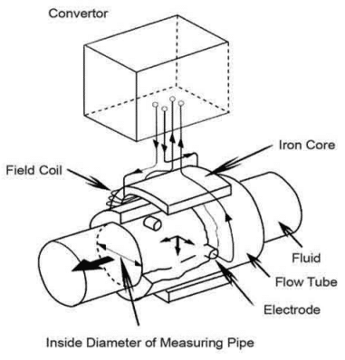
Working principle diagram of electromagnetic flowmeter

Applications

Apure as one of the leading manufacturers of electromagnetic flow meters, we produce products that are competitive in both functionality and durability. Our electromagnetic flowmeters are known for their higher performance and they can handle a variety of liquids with solid particles, such as sewage and milk. Here are some application scenarios:

  • Sewage treatment plant
  • Molasses
  • Coal slurry
  • High mineral water
  • Soft drink
  • Alkali and acid
  • Chemical solutions
  • Medicine
  • Papermaking
  • Petrochemical
  • Metallurgical

Apure offer flowmeter solutions that address complex industrial challenges. Our flowmeter equipment has a reputation for being cost effective, easy to maintain and reliable. If you have any specific requirements, please contact us.

Installation of magnetic flow meter

The installation of magnetic flowmeter has an important impact on the measurement accuracy and instrument stability.

Electromagnetic flowmeter installation diagram

Installation environment

  • Electromagnetic flowmeter should be installed in a dry, ventilated, no vibration, no strong magnetic field, no corrosive gas environment.
  • Avoid direct sunlight, if necessary, should take measures to prevent sunlight.
  • There should be enough space around the flowmeter for easy installation, maintenance and overhaul. ,

Pipe installation

  • Electromagnetic flowmeter sensor should be installed vertically in the pipeline filled with liquid, and the fluid should flow from bottom to top.
  • The sensor can not be installed in the highest position in the pipeline, so as to avoid gas accumulation affects the measurement.
  • In the sensor upstream and downstream should be retained enough straight section, generally 10D ~ 15D.
  • The piping connection should be firm and without leakage.

Electrical installation

  • Electromagnetic flowmeter power supply should be stable and reliable AC power supply.
  • The meter should be grounded to eliminate interference.
  • Signal cable should be shielded and laid separately from the power line.

Electromagnetic flowmeter selection

In the selection of magnetic flow meter, the following factors should be considered:

Fluid characteristics

  • Electromagnetic flowmeter can only measure conductive liquids. Therefore, in the selection should first determine whether the conductivity of the measured fluid is greater than or equal to 1μS/cm.
  • Fluid viscosity, density, corrosivity and other parameters will also affect the measurement accuracy of the electromagnetic flowmeter.

Piping parameters

  • The caliber of the electromagnetic flowmeter should be consistent with the caliber of the pipeline.
  • In the sensor upstream and downstream should be retained enough straight section, generally 10D ~ 15D.

Measurement accuracy

Electromagnetic flowmeter measurement accuracy level is generally 0.5 level, 1.0 level, 1.5 level, 2.0 level.

Functional requirements

Some electromagnetic flowmeter also has Hart protocol, Profibus DP protocol and other functions, which can meet the communication needs of different users.

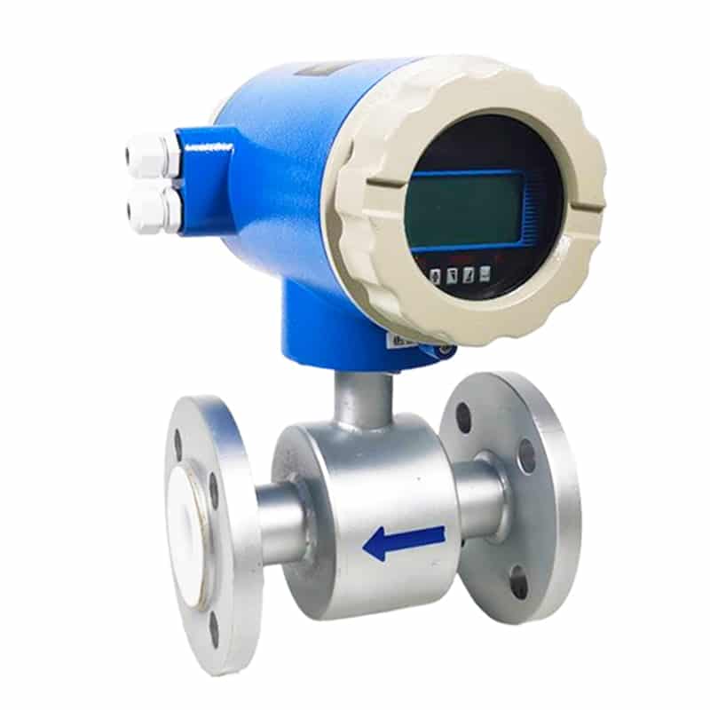
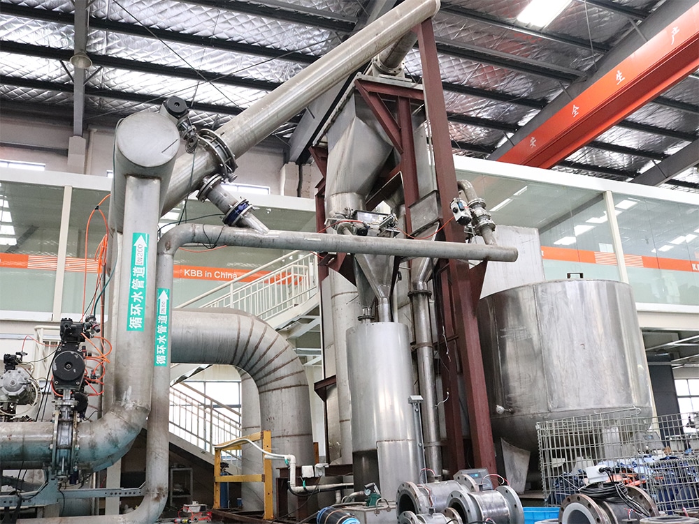
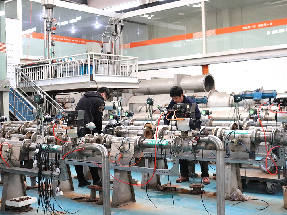
Magnetic flow meter factory

Video

FAQ

Electromagnetic flowmeter inspection mainly check the electrode and excitation coil quality:

1. Check the electrode: use a multimeter to measure whether each electrode is on. A stylus contacts the electrical extreme, and a stylus measures the corresponding terminal in the junction box. I have participated in the industry training, Shanghai new technology Co., Ltd. electromagnetic flowmeter engineering said that this is the simplest way.

2. use a multimeter to detect the quality of the excitation coil: use the resistance of the multimeter to measure the resistance of the coil. The value can neither be infinite nor close to conduction. The normal value should be between tens of ohms and hundreds of ohms (different types of flowmeter resistance may vary).

Electromagnetic flowmeters use magnetic fields to measure the velocity of fluid through pipes to measure volume flow. They are based on Faraday’s law of electromagnetic induction, according to which a liquid generates a voltage as it flows through a magnetic field. The faster the fluid flows, the more voltage is generated. The voltage generated is proportional to the motion of the water; The voltage signal is electronically processed into volume flow to record real-time values.

  1. When the electromagnetic flowmeter is installed on the grounded metal pipe, the system potential balance is realized through the grounding terminal on the electromagnetic flowmeter transmitter, that is, through the copper core wire with a cross-sectional area of no less than 6 mm2 connected to the grounding terminal.
  2. When the electromagnetic flowmeter is installed on the ungrounded metal pipe, the two flanges are connected with the pipe flange through the copper core wire with a cross-sectional area of no less than 6 mm2, and grounded; Connect the transmitter or sensor junction box to the grounding terminal to achieve the potential balance of the system.
  3. When the electromagnetic flowmeter is installed in a plastic pipe or pipe lined with insulation, the system potential balance is achieved by additional grounding ring, and the grounding ring is connected to the grounding terminal through a copper wire with a cross-sectional area of no less than 6 mm2.

Is mainly used to measure the instantaneous flow of the fluid medium, and cumulative flow, and the collected data by communication cable or wireless mode, transmission is the highest level computer operating system or automation control system, by the systematic analysis of the measured data, the corresponding process fluid in the pipeline for handling, the eyes of the flowmeter is known as the industrial automation, Through the flowmeter, the flow rate and other data of the pipeline medium can be known in real time.

  1. The ground point of the sensor output signal should be electrically connected with the measured medium, which is a necessary condition for the work of the electromagnetic flowmeter.
  2. Because the sensor output signal is very small, usually only a few millivolts. In order to improve the anti-interference ability of the instrument, the zero potential in the input loop must be grounded, and the earth potential is zero potential, which is a sufficient condition for the sensor to be grounded. Poor grounding or no grounding wire will lead to external interference signal, leading to sampling error of electromagnetic flowmeter AD converter, error form: air pipe, signal zero or negative signal.
  3. For the connection between the geodetic potential and the earth, this can generally be satisfied because the general metal pipes are connected to the earth and the flowing medium is electrically connected to the earth through the metal pipes.
  1. Determine the corresponding water pump according to the calibre of the pipeline and the flow of the verification test;
  2. After the flowmeter is correctly installed and connected, it should be preheated by electricity for about 30min according to the requirements of verification regulations;
  3. If high trough water source is used, check whether overflow signal of stabilized water tower appears. Before the formal test, the application of verification medium in the pipeline system circulation for a certain time, at the same time to check whether there is leakage in the sealing parts of the pipeline;
  4. the verification medium should be filled with electromagnetic flowmeter sensors before formal verification, and then turn off the downstream valve for zero adjustment;
  5. At the beginning of verification, open the valve at the front of the pipeline and slowly open the valve behind the electromagnetic flowmeter to adjust the flow at the checking point.
  6. In the calibration process, the flow stability of each flow point should be within 1% ~ 2% – flow method, and the total law can be within 5%. The temperature change of the verified medium should not exceed 1℃ when completing the verification process of one flow point, and not exceed 5℃ when completing the whole verification process. The downstream of the electromagnetic flowmeter inspected should have a high enough pressure to ensure that there is no flash and cavitation phenomena in the flow pipeline;
  7. After the test, the valve at the front end of the test pipeline will be closed, and then stop the pump to avoid emptying the pressure regulator. At the same time, the remaining verification media in the test pipeline must be emptied and the control system and air compressor must be closed.

When the measured liquid conductivity reaches a certain value, such as the conditions of the PTEMF electromagnetic flowmeter is: the conductivity of the liquid is greater than 5us/cm, softening water conductivity is greater than 20us/cm, more suitable for use.

Product categories

Popular articles

Liquid flow meter

Liquid flow meter

Measuring liquid flow is a critical requirement for many industrial plants. In some operations, the…
Hot water flow meter

Hot water flow meter

There are two measurement opportunities in heated hot water applications; hot water output leaving the…
Sewage flowmeter

Sewage flowmeter

Sewage flowmeter is composed of water level flow sensor (probe) and upper computer (terminal) and…