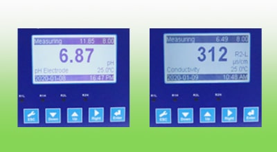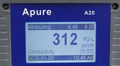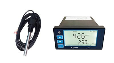
A20 EC Water Conductivity Tester


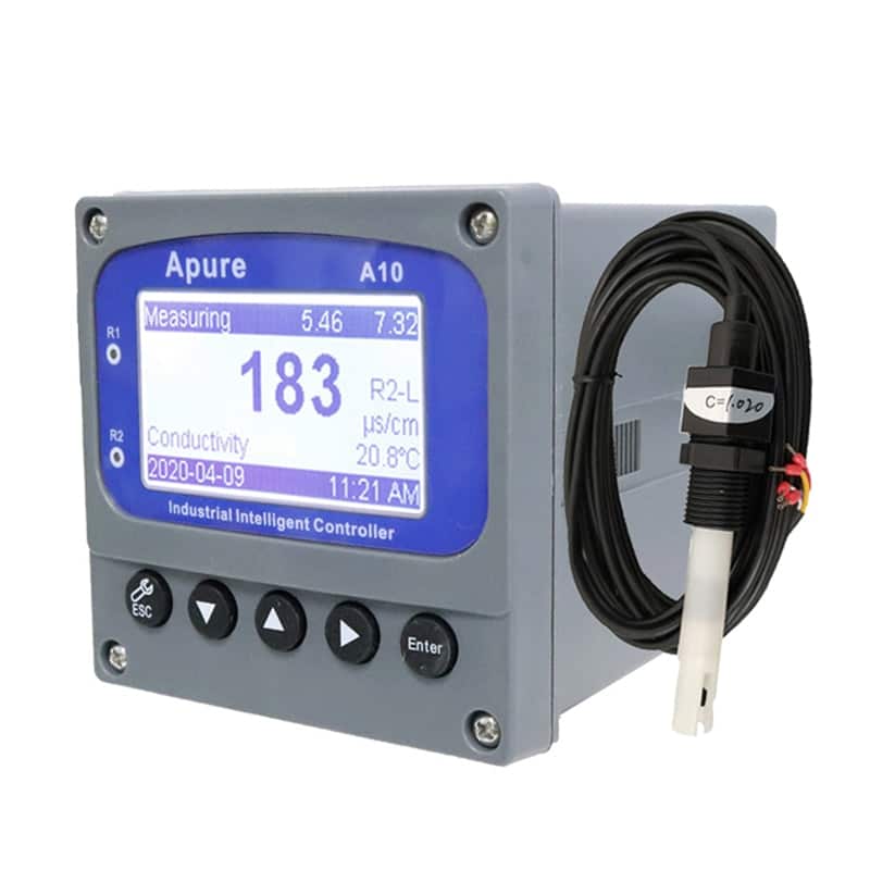
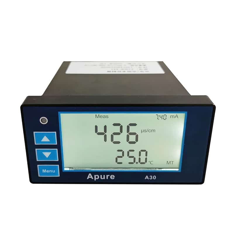
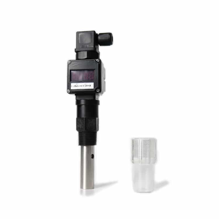
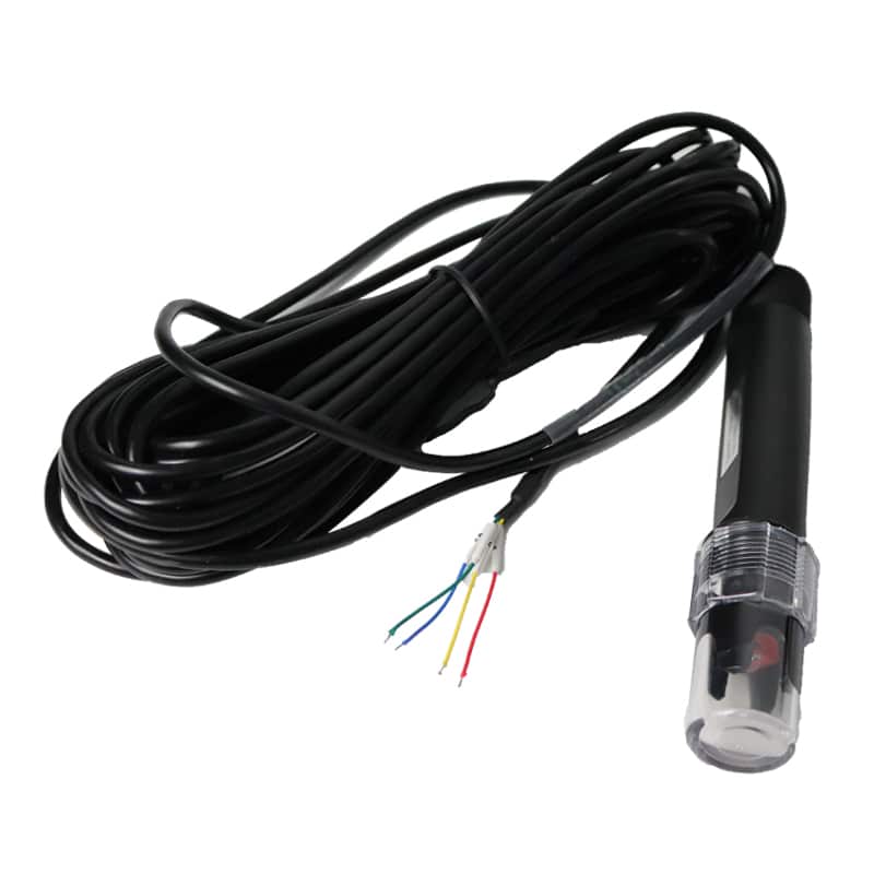
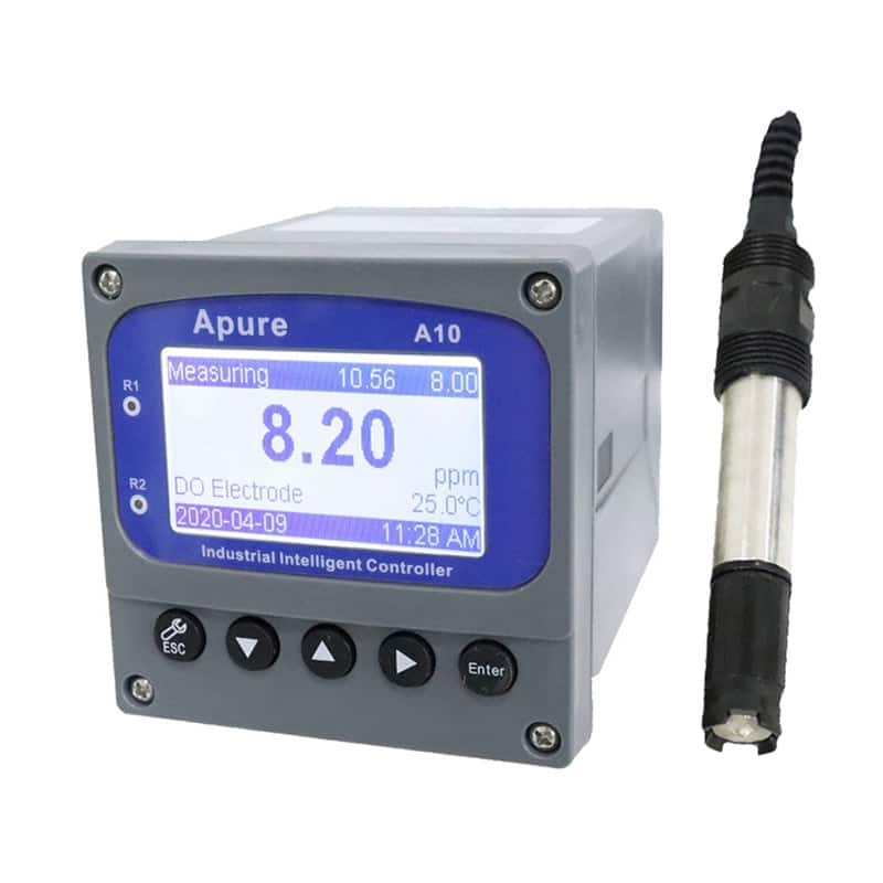
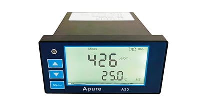
The Apure A20 EC Water Conductivity Tester is an online conductivity controller for a compatible EC probe. Select the probe range, temperature input and required outputs as a complete system. Confirm the supplied A20 EC configuration before ordering or installation.
- Conductivity measurement
- Probe and temperature-input matching
- Output and installation selection
A20 EC system selection
Choose the measuring range around the expected sample conductivity, including normal and upset conditions. Specify the probe cell constant, wetted materials, process temperature and installation method. Controller temperature compensation does not replace the probe’s physical process-temperature rating.
Measurement and commissioning
- Confirm the controller model is A20 EC and the supplied probe is compatible with its input.
- Use the approved version-specific terminal diagram and panel drawing before wiring or cutting an enclosure.
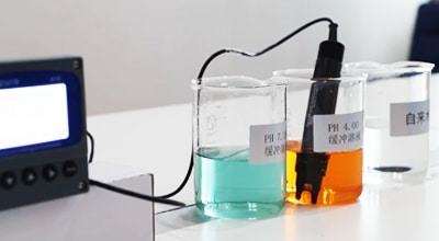
- Calibrate with a suitable certified conductivity standard following the supplied instructions, then verify with an independent check.
- Record EC units, sample temperature, compensation model and reference temperature when comparing readings.
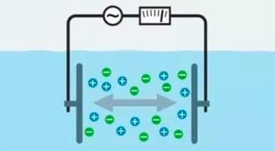
EC is displayed in µS/cm or mS/cm. If a supplied configuration also reports estimated TDS, confirm the conversion factor and water application; a universal conductivity-to-TDS factor should not be assumed. See the EC unit converter and conductivity calibration guide.
A20 EC configuration to confirm
| Item | Selection or confirmation requirement |
|---|---|
| Brand / model | Apure / A20 EC |
| Measured parameter | Electrical conductivity; confirm the supplied range and display units. |
| Probe input | Confirm probe model, cell constant, connector and temperature element. |
| Accuracy and resolution | Obtain values and test conditions for the selected controller-and-probe range. |
| Temperature treatment | Confirm compensation algorithm, reference temperature and separate probe process limits. |
| Outputs and communication | Specify required analog output, digital interface and protocol; confirm included options and wiring. |
| Installation | Use the supplied version-specific outline, panel cutout and terminal diagram. |
The quotation and supplied model documentation should define the final numerical specifications. Do not substitute the specifications of a pH controller or another A-series model.