
Ultrasonic level transmitters are widely used in industrial fields, mainly for non-contact level measurement, such as chemical, petroleum, food, water treatment and pharmaceutical industries. By accurately measuring the level of liquid, solid or powder media, it ensures the safety, stability and quality of the production process, which is of vital importance for industrial production.
Ultrasonic level transmitter introduction
A top-mounted ultrasonic level transmitter sends a sound pulse through the gas space toward the material surface and detects the returning echo. The round-trip travel time and sound speed give surface distance. The configured reference height then converts distance to level. Temperature and gas conditions can affect sound propagation.

The sensor, electronics and enclosure must suit the installation and environment. Use the actual model’s mounting requirements, operating limits and electrical connection instructions.
Ultrasonic measurement can avoid immersing a probe in the liquid, but performance depends on a usable echo and the installation. For the AK2000E and AK7000E, confirm range, blocking distance, temperature limits, process conditions and required accuracy from the supplied documentation. Do not infer immunity to foam, vapor or temperature gradients from the technology name.
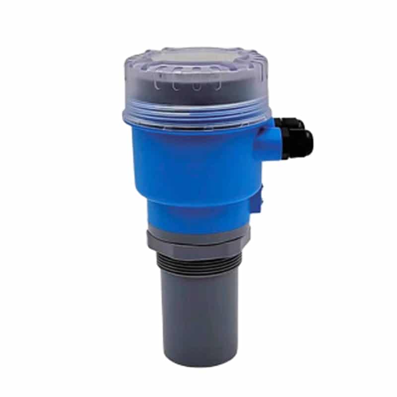

Applicable scenarios include chemical, petroleum, water treatment, pharmaceutical and other various industrial fields. In these fields, ultrasonic level transmitters can be used for level monitoring and control of various liquid, solid or powder media, such as level measurement in storage tanks, reactors, pipelines and other equipment to ensure the safety, stability and efficiency of the production process. Its wide applicability and reliable performance make it an indispensable and important tool in industrial automation and process control.
Calibration of ultrasonic level sensors
An ultrasonic level transmitter usually measures the round-trip echo time through the space above the material. Commissioning must distinguish this measured distance from the level and output values calculated from it. Use the supplied model manual for menu names, limits and permitted adjustments.
1. Establish the reference distances
Identify the sensor’s measurement reference point. Record the distance E from that point to the defined minimum level and the span F from minimum to maximum level. In a simple top-mounted arrangement, level L = E − D, where D is the measured surface distance. Include the installation offsets required by the model. The maximum level must remain outside the specified blocking distance.
2. Inspect installation before changing settings
Check orientation, nozzle geometry, the clear acoustic path and nearby obstructions. Foam, fill streams, agitation, condensation, deposits and gas-temperature gradients can disturb the echo. Verify the temperature channel and application settings. A calibration offset cannot reliably repair a lost or incorrect echo.
3. Compare with known distances and levels
Use a suitable independent reference at accessible, controlled points across the operating interval. Record as-found distance, indicated level and output before making changes. If distance is correct but level is wrong, check the reference height and empty/full setup. If the distance itself is wrong, inspect echo quality and installation before using an adjustment allowed by the manual. Do not invent a universal “time-delay” or “stability calibration” parameter.
4. Configure output and verify the receiving display
For a configured linear 4–20 mA level output, the lower level normally corresponds to 4 mA, not zero current. Check the transmitter and receiving controller use the same range and units. Volume measurement requires the appropriate tank geometry or strapping table as a separate conversion.
Theoretical example: if E = 5.0 m and D = 3.0 m, L = 2.0 m. For a 0–4.0 m linear output, that level corresponds to 12 mA. These assumed dimensions illustrate the calculation; they are not an Apure model specification or an actual calibration record.
5. Treat echo mapping and damping as distinct settings
False-echo mapping, where supported, must follow the manual and the known actual level so that a real surface echo is not suppressed. Damping changes response speed; it does not establish measurement accuracy. Check the response after any change instead of hiding unexplained fluctuations with a large filter.
6. Document verification and maintenance
After any permitted adjustment, repeat the comparison and record as-left results, reference identity, conditions, configuration, output checks and acceptance limits. Investigate a persistent mismatch rather than repeatedly forcing a zero. See the general level calibration guide for the distinction between sensor comparison, adjustment and loop checks.
For an example of documented empty/full reference geometry and blocking distance, see the Endress+Hauser Prosonic M FMU44 operating instructions. Its function codes and numerical limits apply to that instrument and should not be copied into an Apure configuration.
Regular calibration and maintenance of ultrasonic level sensors
Regular calibration and maintenance of ultrasonic level transmitters is essential to ensure their stable and accurate operation. First of all, regular calibration can ensure that the sensor’s measurement results and the actual liquid level to maintain consistency, to avoid inaccurate measurements due to the accumulation of errors. Secondly, maintenance can extend the service life of the sensor, improve its stability and reliability, and reduce production interruptions and losses due to malfunctions.
Set verification and maintenance intervals using the manufacturer’s instructions, process risk and observed drift or fouling. Recheck after installation changes, cleaning that affects the measurement, a configuration change or an unexplained shift. There is no universal six-month or annual interval for every ultrasonic installation.
In addition, regular maintenance of the ultrasonic level transmitter is crucial. Maintenance steps include cleaning the surface of the sensor, checking whether the power supply and signal line connections are loose, and checking whether the sensor is affected by dirt or foreign objects. Regular maintenance can effectively prevent malfunctions and maintain the stability and reliability of the sensor.
Finally, it is recommended that when carrying out calibration and maintenance work, the operation manual and instructions provided by the manufacturer should be strictly followed to ensure the accuracy and safety of the work. Regular calibration and maintenance work can not only improve the performance of the ultrasonic level transmitter, but also reduce the risk and cost of the production process, to ensure the smooth progress of production.
Summary
Regular calibration and maintenance of ultrasonic level transmitters is essential. Calibration ensures that measurements are consistent with the actual level and avoids the risks and losses associated with inaccurate measurements. Maintenance, which includes cleaning the sensor, checking connections and removing dirt, improves the stability and reliability of the sensor.
Apure offers ultrasonic level transmitters as well as magnetic level meters, hydrostatic level sensors, radar level meters and level switches. Please contact us if you have any questions.