
RS-485, also known as TIA-485 or EIA-485, or “Recommended Standard 485”, is a serial communication protocol widely used in industrial and commercial applications. It is a differential signaling protocol, which means that it uses two wires to transmit data: a positive polarity wire and a negative polarity wire. This differential signaling makes RS-485 more resistant to interference and suitable for long distance communication in noisy environments.
What is serial communication?
Serial communication is a data transmission method characterized by the sequential transmission of data bit by bit. It is often used for data exchange between two or more devices. For example, when your computer transmits data to a mouse or printer via a USB cable, it is essentially a kind of serial communication. Or, an Arduino development board connected to a sensor module via a serial port is also a typical application of serial communication.
RS-485 communication principle
RS-485 is a standard commonly used for serial communication and is widely used in industrial automation, control systems and instrumentation. The following is the basic principle of RS-485 communication:
- Differential signaling: RS-485 communication uses differential signaling, which means that the data is transmitted through two wires (usually referred to as lines A and B). Differential signaling means that when the transmitter sends logic 1, the voltage on line A is high and the voltage on line B is low; when the transmitter sends logic 0, the voltage on line A is low and the voltage on line B is high. This differential signaling method is anti-interference because it reduces the effect of electromagnetic interference on the signal.
- Point-to-point or multi-point connection: RS-485 communication can be used for point-to-point connection or multi-point connection. In a point-to-point connection, only two devices communicate with each other. In a multipoint connection, multiple devices can be connected to the same bus, each with a unique address. This makes RS-485 ideal for applications where multiple meters or devices are connected.
- Half-duplex communication: RS-485 usually operates in half-duplex mode, which means that communication can take place between two directions, but not at the same time. At one point, one device can send data while the other device can receive it. The communication direction can then be switched to allow the other device to send data.
- Terminating resistors: Terminating resistors, usually 120 ohms, are usually required to be connected to both ends of the RS-485 bus. These termination resistors are used to prevent signal reflection and ensure signal integrity.
- Communication protocol: RS-485 communication usually requires the use of a specific communication protocol to organize and interpret data. Both communicating parties must agree on the protocol to be used prior to communication to ensure that the data is correctly transmitted and interpreted. Common RS-485 communication protocols include Modbus, Profibus and so on.
- Data transmission: Data is transmitted in the form of data frames on the RS-485 bus. The transmitter encapsulates the data in the data frame and transmits it to the receiver via lines A and B. The receiver receives the data frame and parses the data. The receiver receives the data frame, parses the data and processes it accordingly.
- Error detection and correction: RS-485 communication can include error detection and correction features to ensure data integrity. Common detection methods include parity bits, CRC (cyclic redundancy check), etc. to help detect and correct errors in data transmission.
In summary, the principles of RS-485 communication involve the use of differential signaling to transmit data, support for point-to-point or multipoint connections, and the use of specific communication protocols and data frame structures to ensure that data is transmitted and interpreted correctly. This makes RS-485 a reliable standard for industrial and long-distance communications.
What wires are used for RS-485?
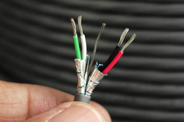
RS-485 communications typically use two wires, called wires A and B. The two wires are used to transmit differential signals and are the basic physical connection for RS-485 communications. These two wires are used to transmit differential signals and are the basic physical connection for RS-485 communication.
- Line A: Line A is a positive polarity wire, responsible for transmitting positive voltage signals. In RS-485 communication, when the transmitter sends logic 1, the voltage on line A is high.
- Line B: Line B is a negative polarity wire, responsible for transmitting negative voltage signals. When the transmitter sends logic 1, the voltage on line B is low.
This differential signaling method is suitable for industrial and long-distance communication environments because of its strong anti-interference performance and ability to suppress common mode noise. The voltage difference between the two wires (the voltage difference between lines A and B) represents the digital data, and the receiving end recognizes the data bits by comparing the voltages of these two wires.
It is important to note that in addition to wires A and B, other wires may be included in RS-485 communications, such as ground (GND) for level reference consistency. Specific connections and cable types may vary depending on application requirements and hardware manufacturers, so specific specific specifications and recommendations need to be followed regarding physical connections in RS-485 communications.
Application areas of RS-485
- Industrial automation and control systems: RS-485 communication is very common in industrial environments and is used to connect a variety of sensors, meters, PLCs (programmable logic controllers) and controllers. It is used to monitor and control factory equipment, processes and production lines, as well as to collect and transmit various process data.
- Building automation: RS-485 communication is used in building automation systems to connect lighting control, air conditioning control, security systems, access control systems and other devices to realize energy management and monitoring in buildings.
- Data acquisition and monitoring: RS-485 is used to connect sensors and data acquisition devices for monitoring various parameters such as environmental conditions, weather conditions, water quality, and gas concentrations. These data are often used in areas such as environmental monitoring, weather forecasting, and scientific research.
- Power monitoring and control: RS-485 communication is used to connect power meters, power monitoring devices, power load management systems, etc., in order to realize the monitoring and control of the power system, including power consumption, power load distribution, and so on.
- Automotive field: RS-485 communication is used in automotive internal systems, such as connecting on-board sensors, dashboard control units, engine control units, etc., for data transmission and vehicle control.
- Telecommunication equipment: RS-485 communication is often used in telecommunication equipment to connect different modules and communication devices for managing and monitoring telecommunication networks.
- Building internet: In building internet, RS-485 communication is used to connect building automation equipments, smart home equipments and security systems to realize intelligent building management and monitoring.
- Remote monitoring and telemetry: RS-485 communication is used to connect telemetry stations, monitoring stations and remote sensors to monitor and control remote equipment and environmental conditions, such as weather stations, hydrological stations, oil field monitoring, etc.
RS485 Function
- Differential transmission mode uses two signal lines (A/B lines) for differential signal transmission, effectively suppressing common-mode interference and enhancing communication stability.
- It supports multi-point communication. Up to 32 nodes (master + slave) can be connected on a single bus, and the expansion chip can support more devices.
- The communication distance is long, up to 1200 meters (at a low baud rate), far exceeding that of RS-232.
- Half-duplex communication, by default, operates in half-duplex mode (only receiving or sending at a time). If two RS-485 channels are used, full-duplex can also be achieved.
- Strong anti-interference ability, differential signal structure + shielded twisted-pair cable, suitable for industrial sites with severe electromagnetic interference.
- It has a high communication rate and can support up to
- Simple wiring and low cost, only two signal lines are required. It supports parallel connection of multiple devices, saving wiring and maintenance costs
How does RS-485 differentiate between different water quality parameters, as well as temperature, pressure, flow and level?
RS-485 itself is a physical layer communication standard that is responsible for the transmission of data and is not directly used to discriminate between different water quality parameters, temperatures, pressures, flow rates, liquid levels, etc. These sensors and instruments transmit the data they measure via RS-485 communications, but the interpretation and differentiation of the data is usually done by the devices (e.g., meters, controllers, data collectors, etc.) connected to the RS-485 interface.
The following are general steps on how to transmit and distinguish different parameters in RS-485 communication:
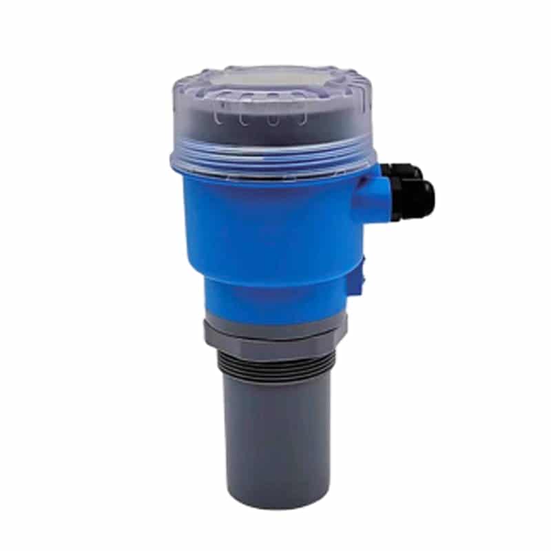
- Sensor selection: First, you need to select a sensor for a specific parameter, such as a temperature sensor, a pressure sensor, a flow sensor or a level sensor(AK2000E Ultrasonic Liquid Level Sensor). Each sensor measures a different physical quantity and converts it into an electrical signal.
- Data format: Sensors typically convert measured values to digital form and encode them into a specific data format. For example, a temperature sensor may output a temperature value (expressed in degrees Celsius or Fahrenheit), and a pressure sensor may output a pressure value (expressed in pascals or pounds force per square foot).
- Data transmission: The sensor transmits the measured digital data to a connected meter or controller via an RS-485 interface.
- Data interpretation: The meter or controller receiving the data needs to know what parameters are represented by the data sent by each sensor. This usually requires configuration in the system to map the received data to a specific parameter type, such as temperature, pressure, flow or level.
- Data display and processing: Once the data has been interpreted to a specific parameter type, the instrument or controller can display the data on the display and perform further processing, logging or control operations as required.
In this process, RS-485 communication is responsible for reliably transmitting the data, while the identification and interpretation of the parameters is done by the device on the receiving end. In order to correctly interpret and differentiate between different parameters, it is important to ensure that the system is correctly configured, including settings such as sensor type, data format and data mapping. Different manufacturers and devices may use different data formats and configuration methods, so settings need to be made according to specific device specifications.
What communication standards are typically used in meters and sensors?
In instrumentation and sensors, the choice of communication standards usually depends on the application requirements, the manufacturer of the device, and the size of the system. The following are some common communication standards that are more widely used in meters and sensors:
- RS-485: RS-485 is a common industrial communication standard, suitable for connecting instruments, sensors, PLC and other devices, especially in industrial automation and control systems are widely used.RS-485 supports multi-point connection and long-distance transmission, and has good anti-interference.
- Modbus: Modbus is a common communication protocol, usually based on RS-485 physical layer. It is widely used to connect industrial devices such as meters, sensors, PLCs and SCADA systems for data acquisition, monitoring and control.
- HART (Highway Addressable Remote Transducer): HART is a protocol used for process control and instrumentation communication. It is typically used with 4-20mA analog signals to allow digital communication and analog signal transmission for connecting smart sensors and instruments.
- CAN (Controller Area Network): CAN is a communication protocol widely used in automotive and industrial control systems. It is used to connect a variety of devices, including sensors, ECUs (Electronic Control Units), meters and controllers.
- Ethernet/IP: Ethernet/IP is a protocol used in industrial automation, which is based on Ethernet technology and allows the connection of various instruments, sensors and control devices in a factory network.
- Profibus: Profibus is an industrial communication protocol used to connect sensors, meters, PLCs and other automation devices. It is widely used in industry, including manufacturing and process control.
- Foundation fieldbus: Foundation Fieldbus is a digital communication protocol for process automation, typically used to connect sensors and instruments for process control and monitoring.
- WirelessHART: WirelessHART is a wireless extension of the HART protocol for connecting wireless sensors and instruments for industrial environments that require wireless communication.
- LoRaWAN: LoRaWAN is a low-power wide-area network protocol typically used to connect sensors and monitoring devices for long-range, low-power IoT applications.
Typically, the selection of a communication standard depends on the following factors:
- Application requirements, including communication distance, data rate, reliability, etc.
- Equipment manufacturer support and compatibility.
- System complexity and size.
- Cost and budget considerations.
The Difference Between RS485 and RS232
| Comparison Item | RS-232 | RS-485 |
|---|---|---|
| Transmission Method | Single-ended (relative to ground) | Differential (between A and B lines) |
| Communication Topology | Point-to-point (1 to 1) | Multipoint (1 to many, up to 32 devices) |
| Communication Mode | Full-duplex | Half-duplex (can be extended to full-duplex) |
| Max Transmission Distance | ~15 meters | Up to 1200 meters |
| Max Data Rate | ~115.2 kbps | Up to 10 Mbps (shorter distance = faster rate) |
| Noise Immunity | Low (susceptible to interference) | High (suitable for industrial environments) |
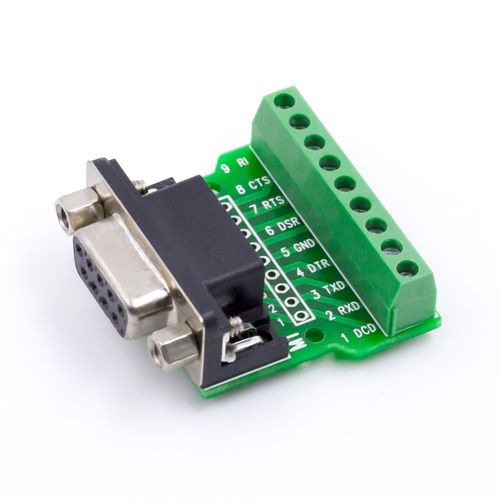
| Wiring Requirement | Typically 3 wires (TX, RX, GND) | Typically 2 wires (A, B) |
| Signal Voltage Level | ±3~15V (referenced to ground) | ±1.5V or more (between A and B) |
| Typical Applications | Serial ports, modems, printers | PLCs, sensors, industrial automation systems |
The Future of RS-485
With the rapid growth of the Internet of Things (IoT), the RS-485 protocol continues to have an important place. While higher speed and more complex protocols have emerged in modern communications technology, the reliability and stability of RS-485 makes it still indispensable in many areas. In the future, as RS-485 converges with IoT technology, it will continue to evolve and develop to meet changing needs.
Summary
The RS-485 communication protocol plays a key role in industrial and commercial applications due to its excellent reliability and versatility. Whether in factory automation, building control, power distribution or other areas, RS-485 provides stable and efficient data transmission. RS-485 still has great potential and will continue to play an important role in the ever-evolving field of technology.
With over 16 years of instrumentation experience, Apure has grown to become a leading instrumentation manufacturer in China and a one-stop service provider for customers worldwide. We provide instruments for water quality analysis, flow meters, level measurement, pressure measurement, temperature measurement, ozone generators and more. Feel free to contact us anytime.
Extended reading:
Water Contamination
Types of level measurement transmitters
3 Main Water Quality Parameters Types
Solution of water pollution